
When the operator introduced a new rig into the region, they quickly identified a performance gap in blowout preventer (BOP) testing. Rigs with several years of experience using IPT Global’s SureTec® PressureTesting solution consistently delivered faster and more reliable results. The new rig had not yet adopted the standardized digital pressure testing workflow required to achieve comparable performance.
The operator’s objective was to bring the new rig up to mature BOP testing performance as quickly as possible while maintaining verifiable well barrier integrity. Achieving this required shifting from variable manual processes to a consistent, documented digital pressure testing approach that reduced risk, minimized inefficiencies, and supported better operational decisions across the fleet.
IPT Global partnered with the operator to implement its PressureTesting solution, provide hands-on coaching, and establish standardized workflows. The result was a rapid improvement in safety and efficiency, with 210 documented pressure tests over the course of 14 months and significant reductions in critical path time early in the campaign.
Each well is unique, making direct comparisons in well barrier testing difficult. BOP testing provided the most practical benchmark because of its central role in safety and operational efficiency. The operator sought two outcomes: absolute confidence in barrier integrity and a reduction in high-pressure test times to minimize operational exposure and risk.
In addition, they wanted a consistent, documented pressure testing practice across the fleet, along with improved transparency between onshore support engineers and offshore execution teams. This was essential to minimize invisible lost communication time during a compressed drilling program.
IPT Global’s leading digital pressure testing software delivers accuracy, efficiency, and consistent assurance across every pressure test.
Adopting new technology requires the right expertise and support. IPT Global ensures customers maximize the value of our solutions through a unique blend of operational experience and data science. Our team combines direct rig experience with specialized software and analytics knowledge, applying technical excellence with practical execution.
IPT Global deployed field coaches to train crews in real operating conditions and ensure consistent, effective use of the software. Once training was complete, our 24/7 Real-Time Operations Center (RTOC) provided continuous support for planning, execution, and oversight. IPT Global also supported the operator by embedding advisors within the wells team and providing real-time visibility across rigs, shore bases, and headquarters.
A key component of the solution was IPT Global’s PressureTesting TestPlanner module – a verification matrix developed alongside drilling engineers as they designed the test plan. TestPlanner provides assurance that every valve and component is tested to the correct pressure. Presented in a clear matrix format, it enables easy identification of optimization opportunities, such as removing unnecessary test steps and ensuring each barrier element is tested in the most efficient sequence.
All 210 pressure tests executed through the wells campaign were documented in standardized format, inclusive of all formation integrity tests (FIT) / Leak off tests (LOT), BOP tests, inflow tests, and completions testing.
Within the PressureTesting solution, pressure data can be captured from existing infrastructure such as cement units, IWOCS, or ROV systems and automatically integrated into the SureTec platform. The PressureTesting DigitalApprovals module removes the inefficiencies of chasing post-test wet signatures or waiting for email confirmations. Our RemoteView module bridges the gap between offshore execution and onshore approval, giving onshore teams real-time transparency into critical wellbore barrier verification. And with the ComplianceReporting module, each test is compiled into an auditable documentation report that can be shared with regulators and incorporated into end-of-well reporting.
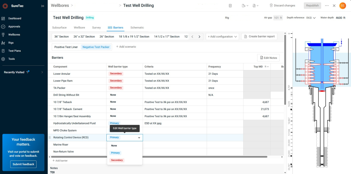
A function that sets IPT Global’s SureTec platform apart is its WellSchematic solution, which provides the ability to generate wellbore and barrier schematics, providing offshore teams with clear, visual representations of the well configuration. For years, describing well configurations relied on complex plans and written instructions. IPT Global streamlines this by automatically importing data from industry-standard well planning software and offering drag-and-drop options. Through the BarrierManagement module, primary and secondary barriers can be assigned, making it easy to visualize which barrier envelope is being tested at each stage, reducing confusion and enhancing operational efficiency offshore.
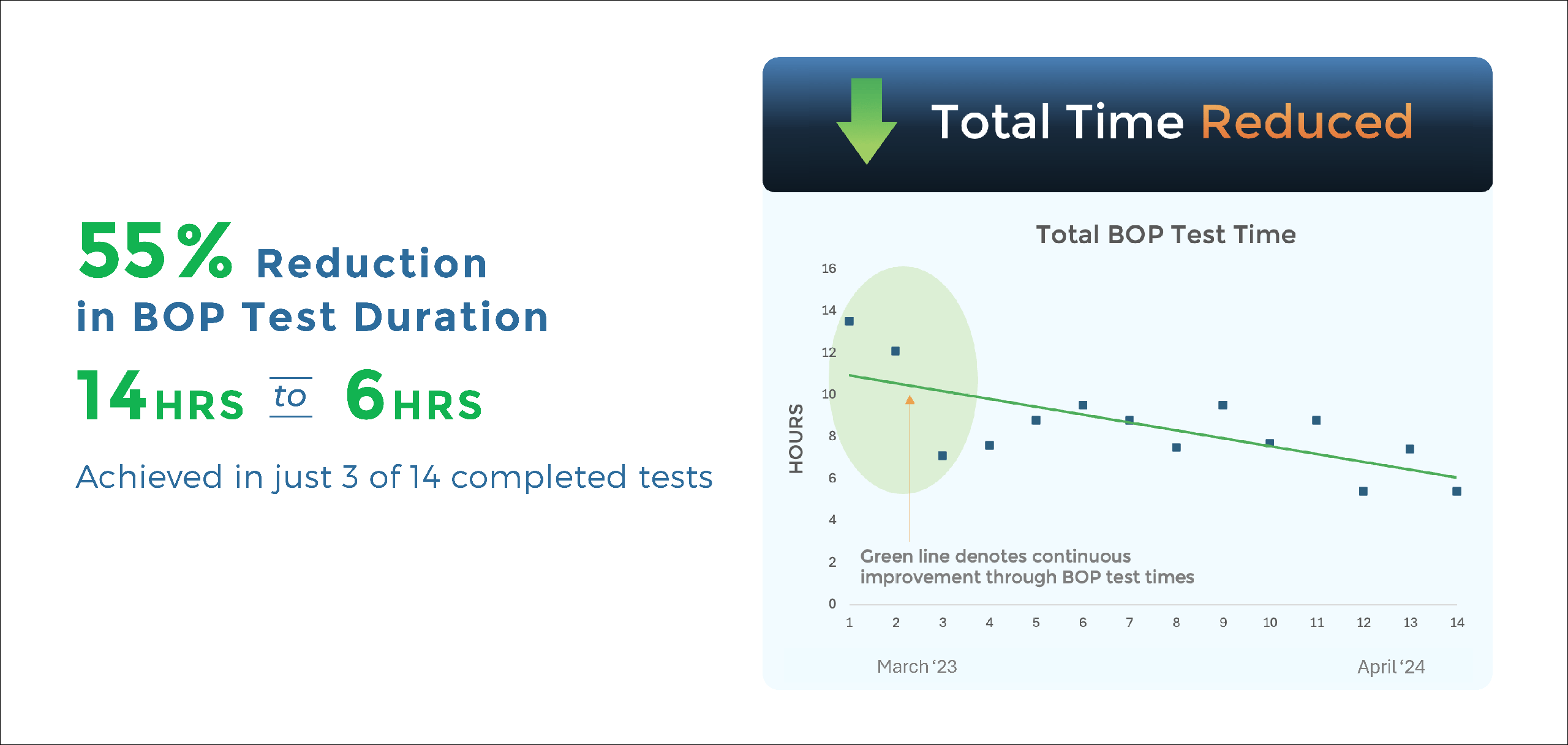
The most significant achievement was the reduction of the overall BOP test sequence from approximately 14 hours to just six hours, and this was achieved after only three BOP tests out of the 14 completed during the campaign. These improvements were driven by a combination of IPT Global’s technology, coaching, and the visual clarity provided by our software solutions.
At the core of this success was our advanced, physics-based analysis, which reduced individual BOP test steps from 17 minutes to eight minutes, delivering more than a 50 percent saving per step. These gains were further supported by TestPlanner, which optimized test planning through our verification matrix, WellSchematic, and BarrierManagement, as well as efficiency improvements achieved through crew training and real-time operational support.
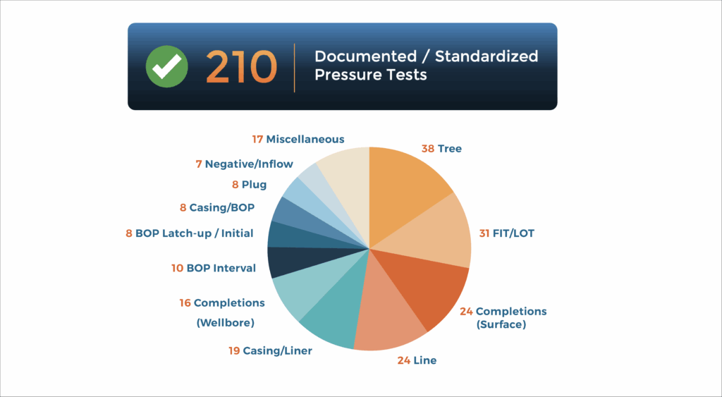
All tests were documented in easy-to-audit reports, ensuring compliance and transparency. While the time savings highlighted here focuses on BOP digital pressure testing, the campaign included 210 documented pressure tests covering the full cycle of drilling and completing these wells.
Importantly, IPT Global’s field coaches were removed from the rig after initial training, with the offshore crew fully supported remotely by our RTOC. This demonstrated that solution adoption and consistent high performance were embedded in the crew and sustained throughout the campaign.
IPT Global provides confidence in every test for every well by applying stringent in-house criteria, delivering faster results than traditional methods, and working collaboratively with customers to drive operational safety and efficiency. Our software ensures information flows seamlessly to the right people at the right time, while WellSchematic and BarrierManagement allow safe planning and execution ahead of operations. All of this is supported by real-time oversight from our RTOC.
Looking ahead, IPT Global will continue to advance well assurance intelligence and software integrations to make our solutions even more accessible and valuable for end users. Contact us to learn how IPT Global digital solutions can help improve your operational efficiencies.
Blowout preventer (BOP) testing is a critical-path operation in drilling programs, but for this major onshore operator, it had become a persistent bottleneck. Average test durations exceeded six hours per BOP test, increasing non-productive time (NPT) and creating schedule challenges.
Beyond timing, the operator’s legacy methods, including circular chart recorders and outdated digital systems, made improving BOP testing efficiency increasingly difficult. These outdated tools often failed to capture complete assurance data, leaving quality issues undetected and complicating BOP testing compliance with API Standard 53.
The operator needed a digital solution to reduce BOP test time, improve BOP testing accuracy, and provide complete traceability across its rig fleet while supporting safer and more reliable well operations.
To address these challenges, the operator implemented IPT Global’s SureTec platform and its PressureTesting digital solution, designed to improve BOP testing workflows across its onshore rig fleet. Third-party testing companies used SureTec laptops at the rig site, while IPT Global’s Real-Time Operations Center (RTOC) in Houston provided remote technical support as needed. The solution’s high-resolution, real-time pressure data replaced manual readings and outdated tools to eliminate uncertainty and mitigate human error.
Automated validation and digital reporting streamlined the entire process, producing faster, more accurate, and fully verifiable results.
By digitizing and automating pressure test workflows with PressureTesting, the operator achieved a measurable step-change in operational efficiency. The solution replaced manual data capture and outdated systems with precise, real-time pressure data and automated validation tools. This transformation directly translated into faster test cycles, reduced rig downtime, and measurable gains in BOP testing efficiency.
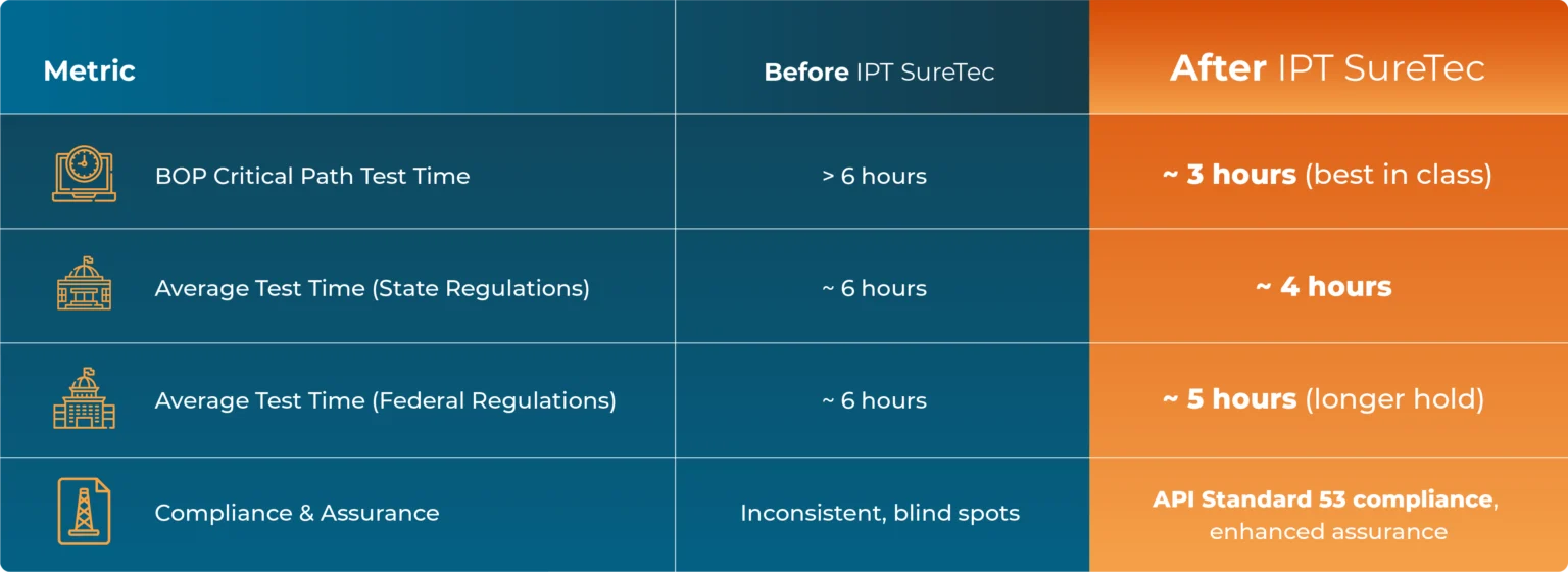
This performance represents a best-in-class reduction in test duration, significantly cutting overall BOP testing duration and improving rig uptime.
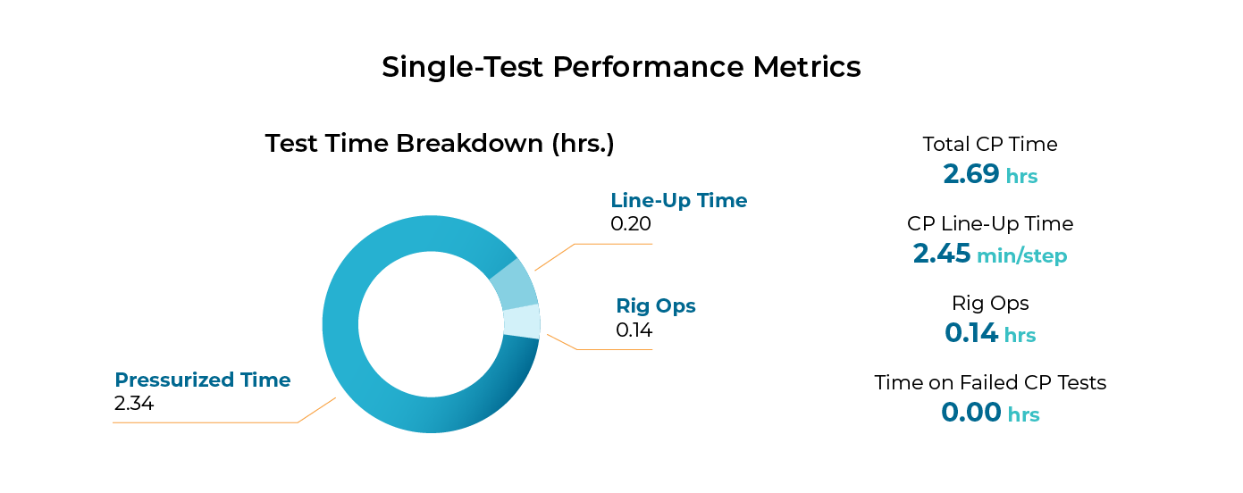
The charts below indicate a decreasing trend over a 4-year period for Total Test Time, Line-Up Time, and Rig Ops Time as a result of optimized BOP testing and learnings from the implementation of PressureTesting. The continued improvement is indicative of the ongoing value and effectiveness of IPT Global’s digital solutions.
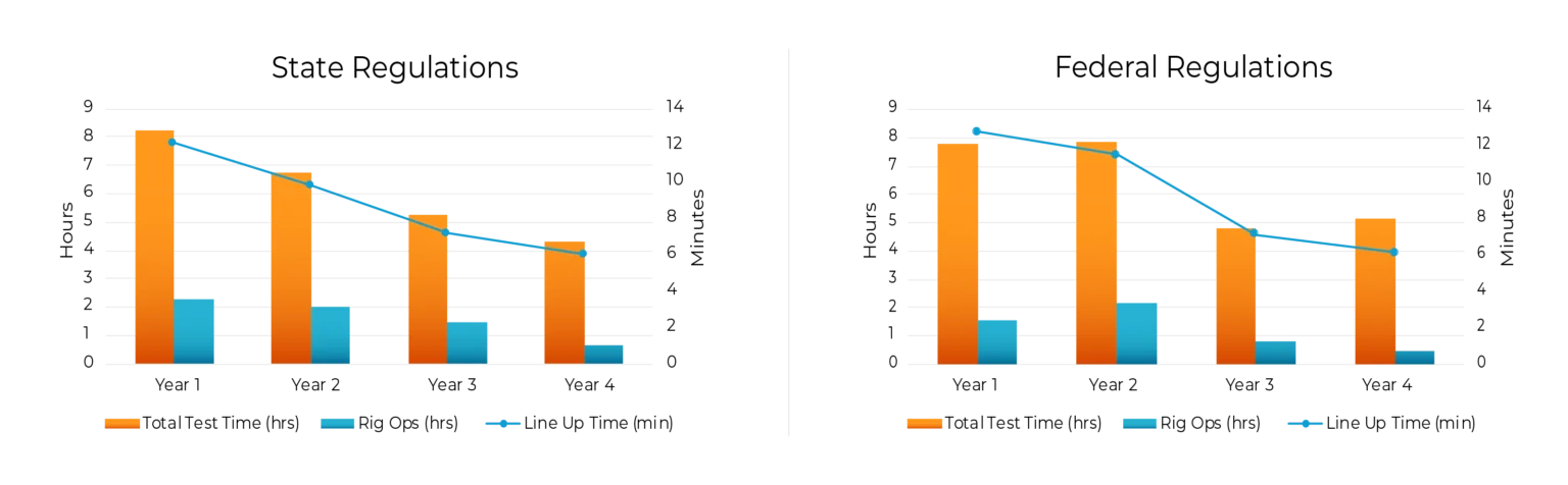
Consistent, verifiable test data and analysis is critical for maintaining compliance and preventing quality issues. With PressureTesting, the operator gained full traceability into every test event, allowing early identification of irregularities and ensuring that every BOP test aligned with API Standard 53 requirements.
The chart below compares average BOP critical path test times for rigs under state and federal regulations. Despite longer federal hold requirements, SureTec’s PressureTesting maintained shorter average times and tighter variability, demonstrating consistent performance under all compliance conditions.
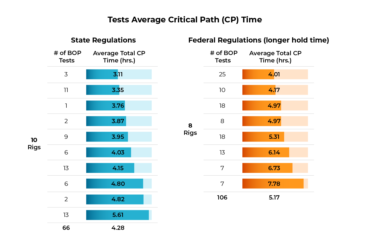
SureTec’s centralized digital test records allowed the operator to monitor trends, analyze test performance, and make real-time data-driven decisions faster than ever before. Over time, this capability improved its well integrity management program and established a culture of continuous improvement across rigs and over multiple years of operation.
What began as an effort to reduce BOP test time resulted in a transformation of the operator’s BOP testing workflow. With SureTec PressureTesting, the operator not only achieved faster testing but also improved quality control, regulatory compliance, and data visibility, which improved well integrity management across its entire rig fleet.
Today, IPT Global’s SureTec PressureTesting solution is setting the benchmark for improving BOP testing efficiency and helping operators reduce BOP test time across both onshore and offshore environments. The digital solution continues to set the standard for BOP testing accuracy and assurance, enabling operators worldwide to improve efficiency in BOP testing operations. Contact us today to schedule a PressureTesting demo.
The oil and gas (O&G) industry generates vast amounts of data at every stage of the well lifecycle: exploration, drilling, completion, production, and decommissioning. Yet much of it remains siloed and underutilized. The Open Subsurface Data Universe (OSDU™) addresses this challenge by providing a common framework for storing, accessing, and exchanging information across workflows.
At IPT Global, we believe the future of well assurance depends on combining advanced digital solutions with industry-wide standards. By aligning well integrity and operational data with these standards, operators gain new ways to improve efficiency, ensure compliance, and strengthen safety.
The OSDU Forum, launched by The Open Group, provides a neutral space where operators, service companies, and technology providers can standardize the way subsurface and operational data is structured, accessed, and shared. The Forum’s goal is to establish a common data platform that removes silos and promotes interoperability across digital tools.
Through this collaboration, the Forum unites operators, service companies, and software providers to create shared standards and reference implementations, forming the foundation for managing and exchanging energy data.
The OSDU Data Platform is an open-source, technology-agnostic environment created to eliminate silos and establish a single source of truth for subsurface, well, and operational data.
By providing a secure, scalable foundation, the framework makes information more accessible to operators, service companies, and regulators. This integration drives collaboration, speeds decision-making, and enables advanced digital solutions at scale.
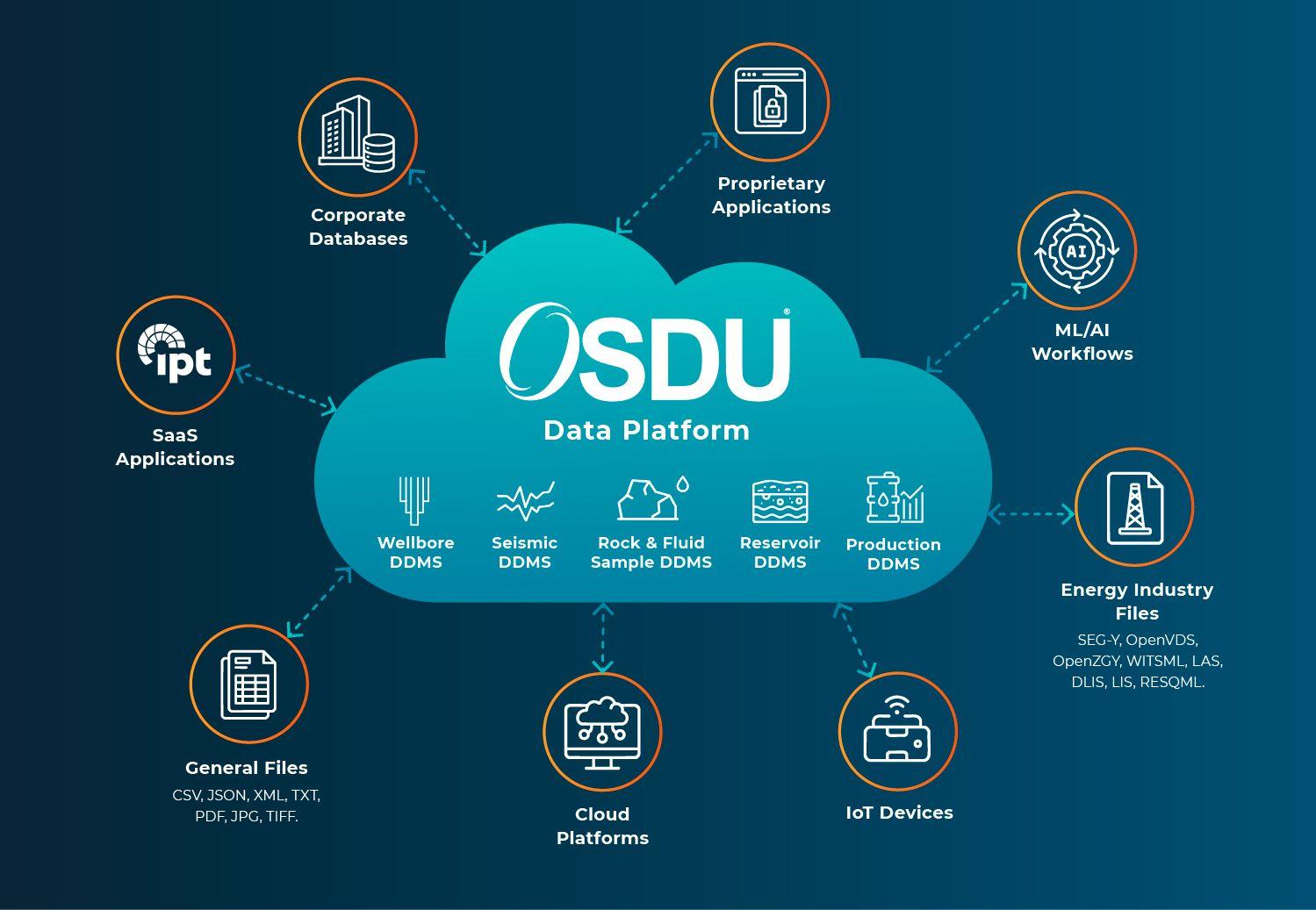
Oil and gas companies face persistent data management challenges, including siloed information, inconsistent formats, limited accessibility, and difficulties collaborating across operators, service companies, and regulators.
The OSDU data platform addresses these challenges by providing standardized frameworks and integration across workflows. Adoption of OSDU enables better data accessibility, faster decision making, lower costs, and a foundation for advanced analytics like AI and machine learning.
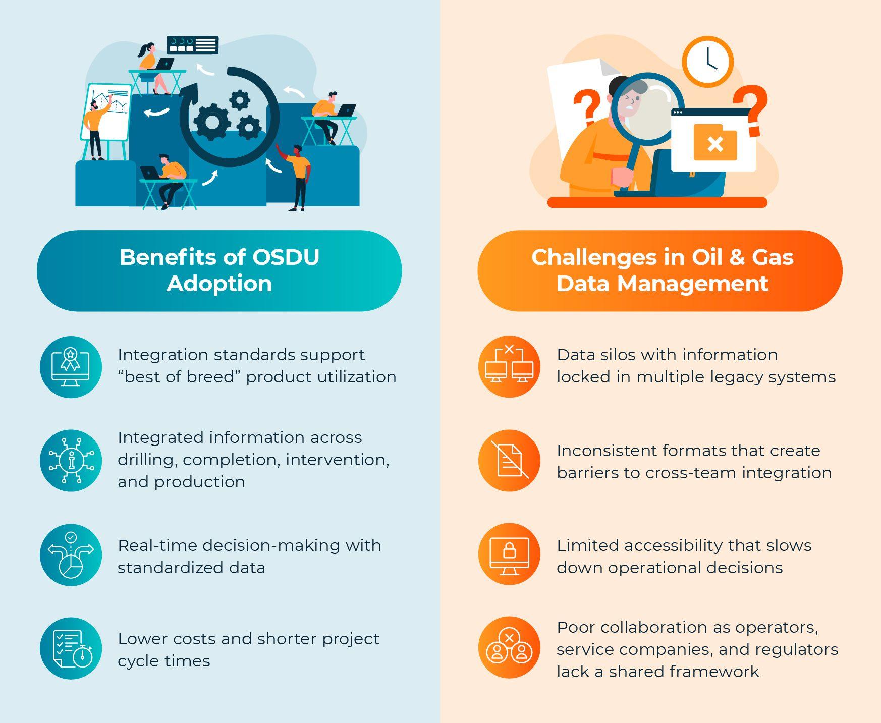
The strength of OSDU lies in its reference architecture and standardized data schema. These define how subsurface and operational information is structured, ensuring it can flow seamlessly between different software and workflows.
At IPT Global, we actively contribute to this effort. Our teams have shaped the schemas for Well Barrier Element (WBE) and Well Control Equipment (WCE) Pressure Tests and Well Schematic Diagrams, which are now part of the OSDU reference implementation. This work standardizes well integrity data and contextualizes it for use across drilling, completion, and abandonment workflows.
By working within the OSDU architecture, IPT Global eliminates inefficiencies of custom integrations and positions data for advanced analytics and automation.
As an active member of the OSDU Forum, IPT Global collaborates with industry leaders, technology providers, and regulators to advance open data standards. Together with other OSDU members, we contribute expertise in well assurance, pressure testing, wellbore schematics and barrier management to shape how operational data is stored and exchanged.
This role delivers IPT Global clients access to data models designed with real-world assurance workflows in mind, allowing them to adopt OSDU more efficiently and with greater value.
Our standards-based approach extends into IPT Global technology. Through secure application programming interfaces (APIs), we integrate well data, incorporate pressure test results, and connect with cloud-based data lakes. Built on service bus architecture, these integrations deliver information that is consistent, traceable, and actionable across planning, execution, and real-time operations.
By aligning our well integrity and barrier management solutions with the OSDU platform, IPT Global makes assurance data practical and accessible across day-to-day workflows.
The OSDU standard is transforming how oil and gas companies manage and use operational data. By replacing fragmented systems with a unified platform, operators can unlock greater value from their information and more effectively adopt advanced digital technologies.
At IPT Global, we put these standards into action. From structuring assurance data and standardizing formatting to embedding well integrity information into daily workflows, we provide the expertise and tools for end-to-end assurance.
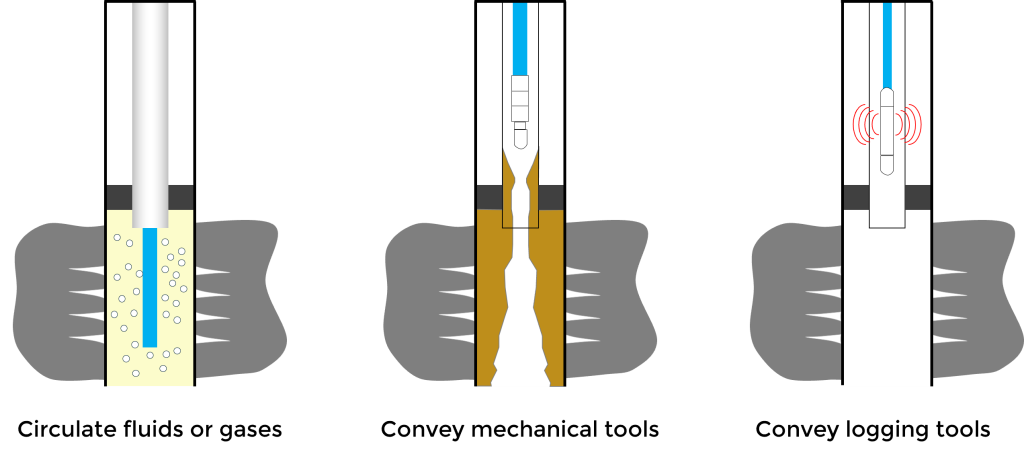
Coiled tubing is a long, flexible, metal or composite pipe with no joints that is used in the oil and gas industry for a variety of purposes:
Coiled tubing has several advantages, including increased efficiency, cost effectiveness, and safer operations. Some of its disadvantages include limited depth and borehole size, high maintenance costs, and reduced accuracy. This article describes the operation and applications for coiled tubing units (CTUs), and it specifically covers the well control stack and industry recommended practices for pressure testing coiled tubing.
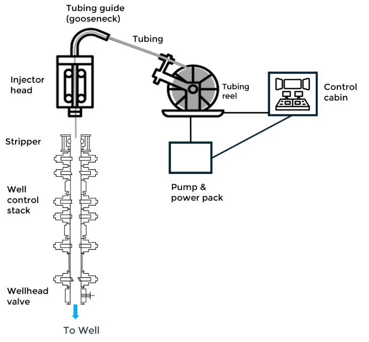
Coiled tubing units (CTUs) include the following components:
Coiled tubing can be used for drilling operations without the use of drill pipe and a rotary table, which speeds up the process. A bottom hole assembly (BHA) with a drill bit is connected to the coil tubing and inserted in the well. The injector head pushes the tubing into the well and the BHA uses a motor or rotary steerable system that rotates the drill bit. The BHA is essential for directional drilling and wellbore navigation.
A downhole mud motor may also be used in coiled tubing drilling operations to convert the hydraulic energy of the drilling fluid into mechanical energy to rotate the drill bit independently of the coiled tubing string.
Coiled tubing is a beneficial tool for circulation in well interventions due to its continuous length’s ability to navigate complex wellbores. Most often, the operation will involve pumping nitrogen or various fluids to free the well of light debris (sand) and removing water or condensates built up during production.
Coiled tubing allows the deployment of logging tools into the wellbore to collect data about the formation and well conditions, such as formation pressure, fluid composition, temperature, and formation properties. This is especially useful in highly deviated or horizontal wells where traditional wireline logging might be challenging.
Subsea lubricators dictate the length of perforating guns that can be run when using conventional drill pipe. Coiled tubing simplifies perforating operations by allowing the use of long BHAs while maintaining dual well control barriers. This enhances safety and operational efficiency.
Coiled tubing can be connected to pumping units and inserted in a well to pump fluids for various treatments, including well stimulation, hydraulic fracturing, acidizing, and cementing. The ability to pump the fluid without interruption while continuously inserting the coiled tubing allows a steady and controlled flow rate.
Coiled tubing can be used for various production enhancement techniques, such as gas lift or artificial lift systems, contributing significantly to improved efficiency and reduced downtime. In gas lift installations, coiled tubing enables more efficient and precise placement of gas lift valves along the tubing string, especially in deep or deviated wells. In artificial lift systems, coiled tubing significantly reduces installation time for electric submersible pump systems in shallow gas wells to address liquid loading issues.
Coiled tubing is valued for its flexibility, efficiency, and ability to perform a wide range of tasks without the need for a rig, making it an essential tool in offshore well interventions.
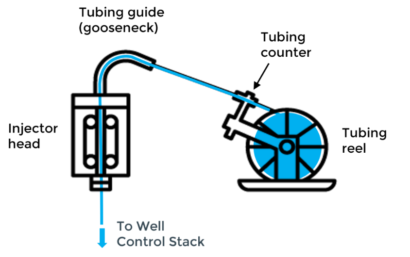
The coiled tubing operator in the control cabin manages the entire process of deploying and retrieving the tubing during coiled tubing operations. Coiled tubing is spooled off the reel and passes through a tubing counter that measures the length of the tubing being deployed and retrieved. The tubing is then guided through a gooseneck and directed downward to the hydraulically driven injector head, which the coiled tubing operator uses to control the movement and depth of the coil tubing string. The tubing becomes straight before it enters the well control surface stack.
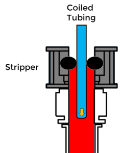
Beneath the injector head, the stripper assembly on top of the well control stack provides a dynamic seal around the tubing string, which is crucial for running the coiled tubing in and out of live wells.
During intervention operations, coiled tubing can be used to circulate acid, nitrogen, or cement. Devices may also be conveyed down the tubing for purposes such as sealing, cleaning, or initiating other downhole operations. For example, balls may be pumped down the tubing to isolate sections of the well, or darts may be used to trigger tools and other chemical treatments. The CTU uses hydraulic pressure to push these devices down the tubing and through a dual-flapper check valve. The flow of hydraulic fluid is carefully controlled to ensure the devices travel to reach their target accurately. Coil tubing also allows logging tools to be deployed down the wellbore to collect data about the formation and well conditions. The coil tubing operator monitors the movement of devices in real time using sensors and telemetry systems.
At the end of the operation, the tubing is pulled out of the well and spooled back onto the reel. A high-pressure swivel joint on the reel hub allows fluid to be pumped while the reel rotates.
Coiled tubing operations are governed by regulatory standards and recommended practices to ensure safety and efficiency. Key standards and recommended practices are 30 CFR Part 250 Subpart G and API RP 16ST, respectively. 30 CFR Part 250 Subpart G is a mandatory federal regulation for outer continental shelf operations, whereas API RP 16ST is a voluntary industry standard. The recommended practices in API RP 16ST offer detailed guidance to support and enhance compliance with the regulations set forth in 30 CFR part 250 sub part G.
API RP 16ST (Recommended Practice for Coiled Tubing Well Control Equipment Systems) is a crucial standard governing coiled tubing operations. The second edition, along with its Addendum 1 from February 2022, provides updated guidelines for well control equipment systems used in coiled tubing operations to ensure enhanced safety and operational efficiency. A summary of some of the key sections of the recommended practice are listed below.
A coiled tubing well control barrier is defined as a tested mechanical device, or a combination of devices, designed to prevent the uncontrolled release of wellbore fluids.
Key components include:
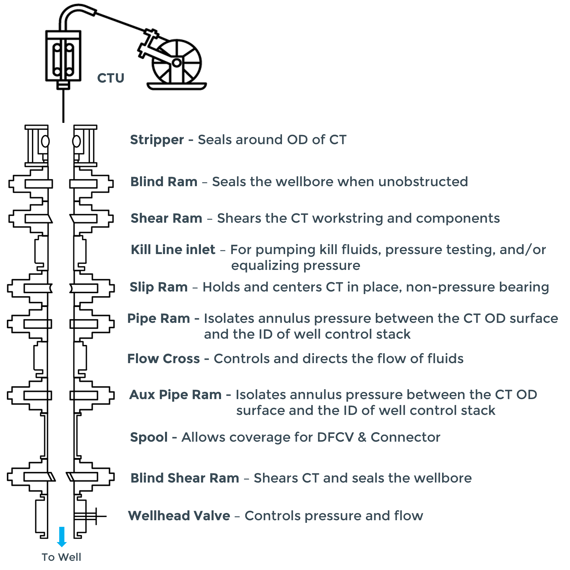
This section outlines the recommended order of components in the well control stack from the top down:
1. Stripper Well Control Component
2. Blind Ram Component
3. Shear Ram Component
4. Kill Line Inlet
5. Slip Ram Component
6. Pipe Ram Component
7. Dedicated SBR Component
All well control equipment must undergo pressure testing.
The well control stack plays a critical role in flow control and well control in CTUs by sealing off the wellbore to contain unexpected flow and high pressures during drilling, production, and intervention operations. A typical well control stack used for coiled tubing operations is shown below. Actual stack configurations may vary based on the operator and the conditions encountered during coiled tubing operations.
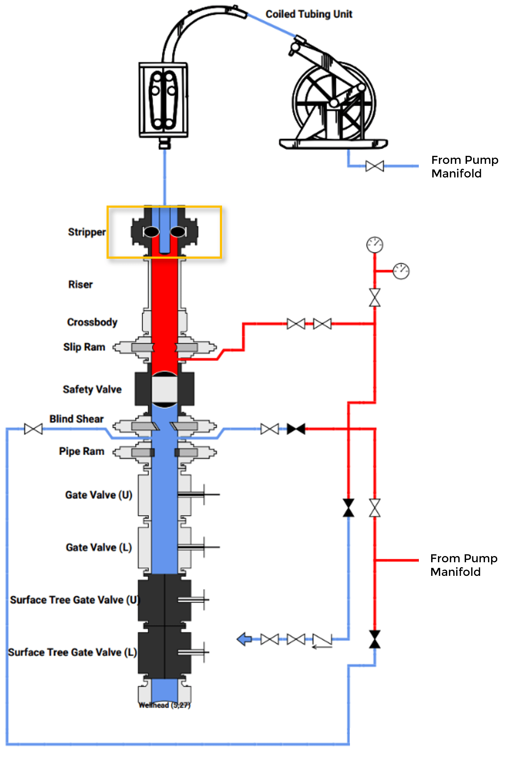
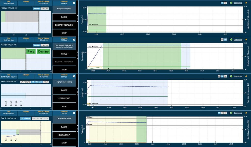
As stated in the API RP 16ST, all well control equipment components should be pressure tested every seven days. The pressure test sequence for each component consists of a low-pressure (LP) test, followed by a high-pressure (HP) test. A component passes the LP test (from 250 to 350 psi) if the pressure stabilizes with no visible leakage for at least five minutes. The component then passes the HP test (MASP plus 500 psig) if the pressure stabilizes with no visual leakage for a minimum of 10 minutes and does not decrease below the intended test pressure. It can take several pressure test attempts to test all of the well control components. The figure below shows the stripper being pressure tested.
It’s common to pressure test multiple tools during a single well control stack test to improve testing efficiency. This is done by testing one tool, disconnecting the assembly, installing a second tool, and then reconnecting the assembly. Typically, the test plan will need to include steps after this process that verify the connection point. Similarly, tools that are meant to stop pressure from coming up the coil (i.e. dual flapper check valves, wash heads, etc.) will usually need to be verified during the pressure test.
CTUs play a critical role in oilfield operations, providing a range of applications from drilling to interventions. Coiled tubing’s flexibility and efficiency make it a valuable tool for optimizing well performance and maintaining well integrity. For details on how IPT Global’s SureTec® Platform supports coiled tubing pressure testing, contact us today.
The formation integrity test (FIT) is one of three types of formation strength tests, and it is used to evaluate the strength and integrity of a newly drilled section of well formation. After setting a section of casing and drilling out the casing shoe, several feet of new formation is drilled and the formation is gradually pressurized to a pre-determined pressure and then held during a subsequent shut-in stage. The FIT data is analyzed to verify the bonding strength of the cement around the casing shoe and to determine the maximum mud weight that can be used to drill the next well section. This test is essential to ensure that the formation can withstand the pressures it will encounter during drilling and production operations and to avoid loss of well control.
The integrity of a wellbore changes with every drilled foot of depth, and mud weight is the sole pressure mechanism keeping the borehole stable. Formation Integrity Testing is vital for maintaining well integrity as it helps prevent well control issues like blowouts and other hazardous events. In addition to verifying the maximum mud weight needed to drill the next well section, a formation integrity test is used to compute the minimum mud weight required to prevent hole collapse and to evaluate the quality of the cement bond around the casing shoe. By verifying the formation’s ability to hold pressure, avoiding hole collapse, and assuring cement integrity, operators can substantially improve the safety and efficiency of drilling operations.
There are three types of formation strength tests used to evaluate the strength and integrity of a newly drilled well section: the standard Formation Integrity Test (FIT), the Leak-Off Test (LOT), and the Extended Leak-Off Test (XLOT). The different uses and procedures for these tests are described below.
Essential safety measures during FIT include:
After the casing or liner is cemented and before drilling out the cement at the shoe, a casing integrity test (CIT) is typically run to ensure the integrity of the casing or liner. During the CIT, drilling fluid is pumped into the casing or liner. The shut-in valve is closed when the target pressure is reached (below the maximum allowable pressure). If the pressure analysis passes specific criteria, the CIT is successful.
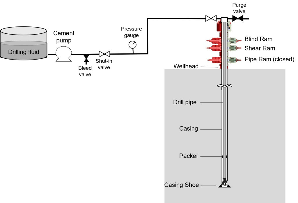
FIT guidelines are established to ensure that the FIT tests are performed consistently, safely, and accurately. The guidelines below are used for reference during the test and subsequent FIT analysis.
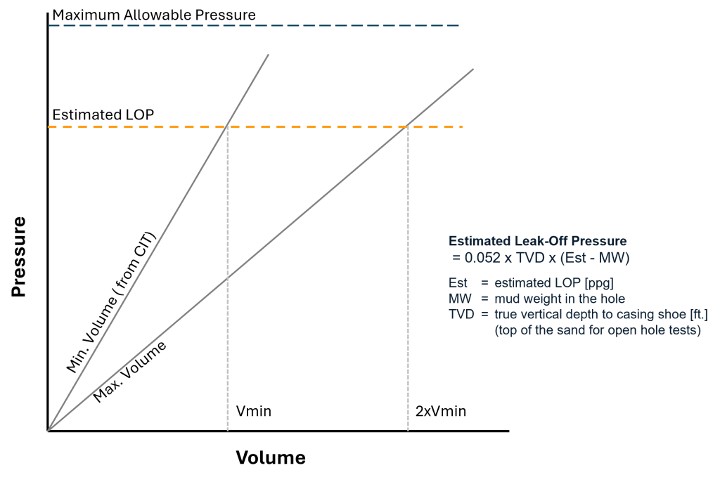
Following a successful casing integrity test, a standard formation integrity test (FIT) involves gradually increasing the bottom hole pressure to a predetermined level to check the formation’s ability to withstand the pressure without leaking off drilling mud. Following a successful casing integrity test, FITs are generally performed using the following steps:
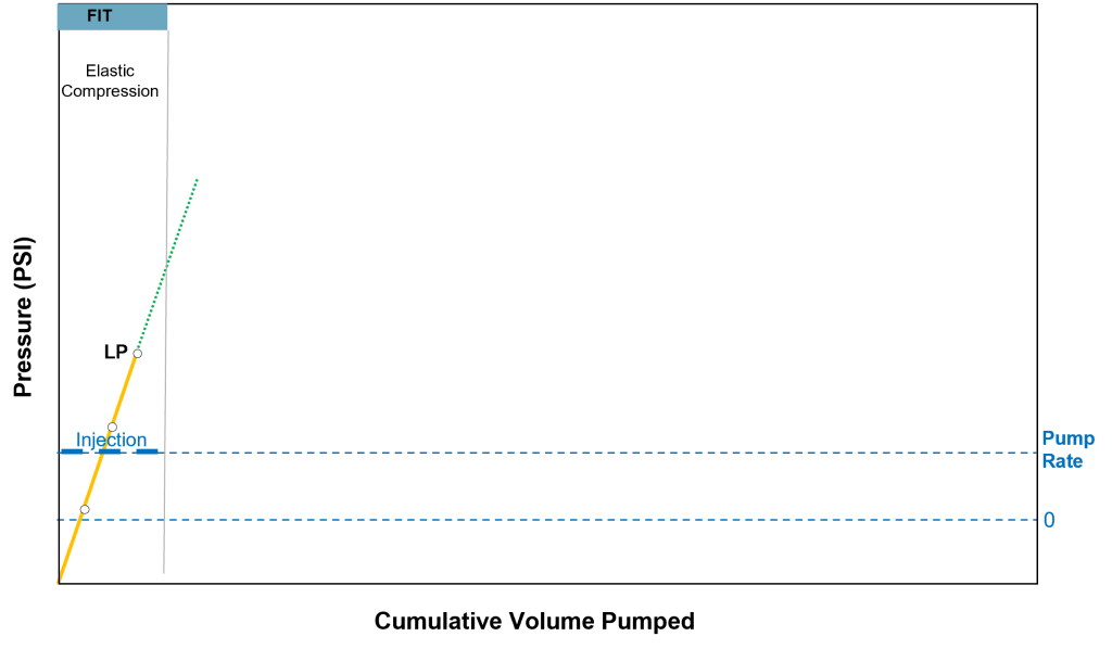
A Leak-Off Test (LOT) is performed to determine the exact pressure at which the formation begins to fracture. It is often conducted at various depths during the drilling process to assess the formation’s pressure containment capacity. The key difference between the LOT and standard FIT is that the LOT involves a controlled increase in pressure until a small amount of fluid leaks into the formation, indicating the fracture point. This information is valuable for more accurately estimating formation stresses, which can be used to optimize the number of casing strings required.
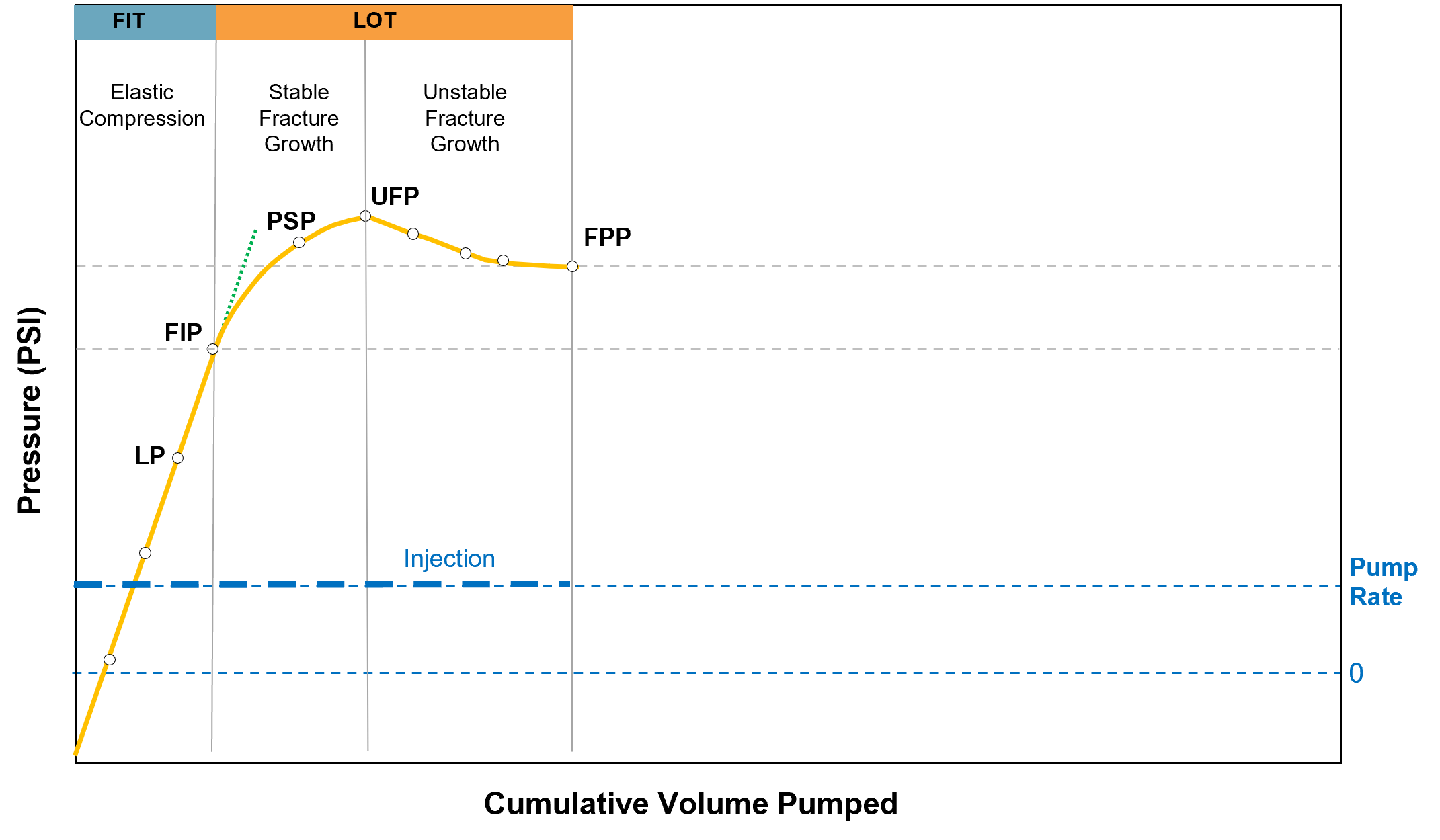
For a typical LOT, pressurization is continued past the LP until the wellbore pressure induces a stable fracture in the formation (fracture initiation pressure). When the crack opens, fluid is lost to the formation across the permeable faces of the fracture. These fluid losses lead to smaller increases in pressure as additional fluid is pumped, which is indicated by the change in slope of the plot at a point called the fracture initiation pressure (FIP). The rising pump pressure at the surface up to the pump stop pressure (PSP) indicates stable fracture growth, as fluid is lost along the length of the fracture. After PSP, the fracture becomes unstable at a point called the unstable fracture pressure (UFP) because the fracture is extended away from the wellbore. When the pressure begins to asymptotically level off at the fracture propagation pressure (FPP), the test is concluded. Drilling operations then typically resume if the tests results permit the use of a suitable mud weight and if no cement channels are detected.
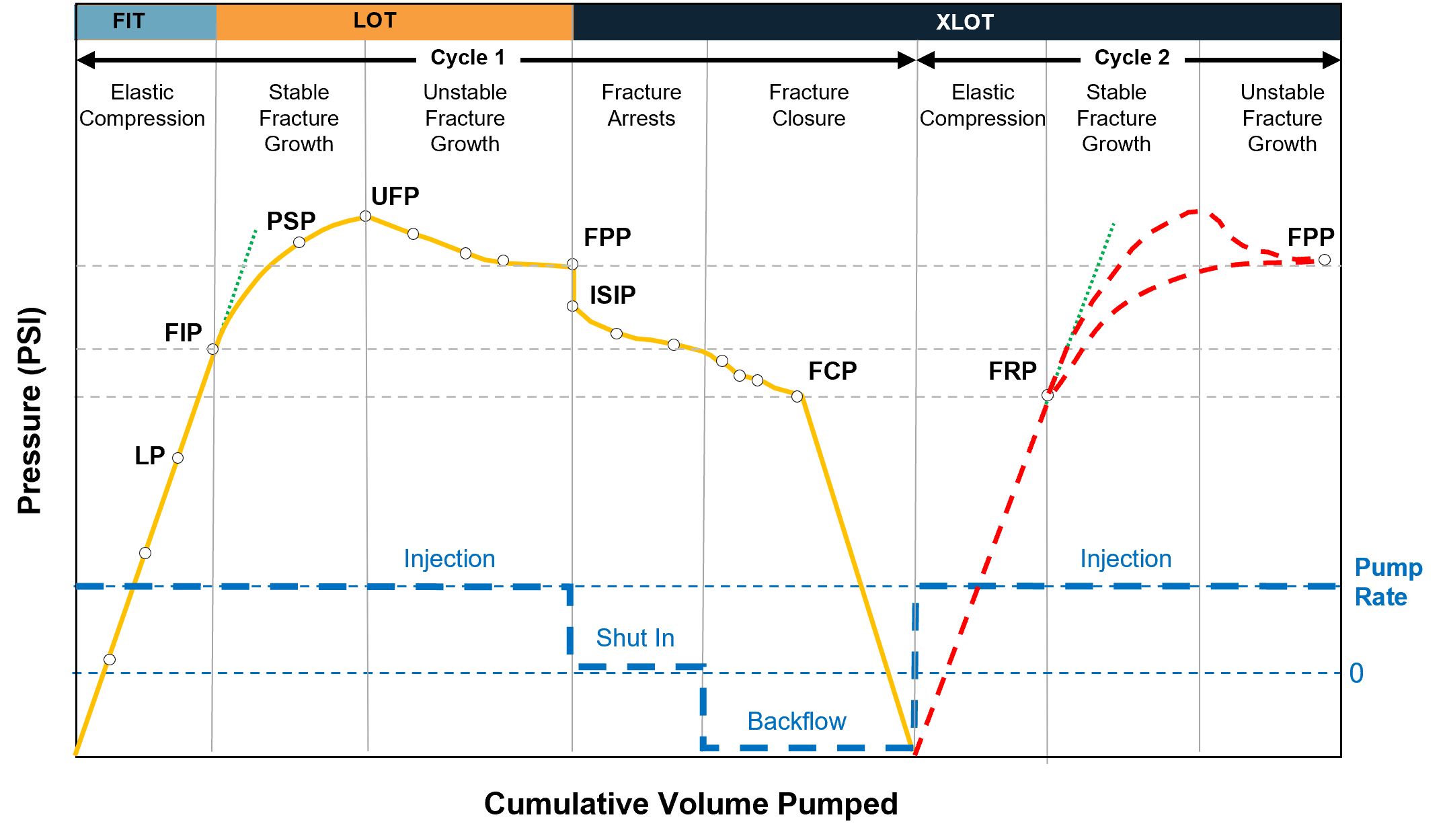
The Extended Leak-Off Test (XLOT) is a series of LOTs that may be run to obtain horizontal stress data for predicting wellbore stability. The XLOT is a longer and more comprehensive test in which the mud continues to be pumped after the FIP is reached to determine the fracture closure pressure. Chronologically, the XLOT process consists of the following stages:
This process can be repeated multiple times to open and propagate the fracture to gather more data. The figure below shows an XLOT with a repeating cycle.
The results of a FIT are typically analyzed by visually interpreting pressure versus time and pressure versus volume plots, or by comparing them with theoretical models of formation behavior under stress. Key indicators of well integrity from FIT results include:
To accurately analyze LOTs and XLOTs, multiple factors should be considered, such as formation permeability, fluid compressibility, stresses around the wellbore, and mud type.
The following factors can distort FIT, LOT, and XLOT results and lead to interpretation difficulties.
Although the LOP is defined as the point where the trend of the pressure increase deviates from linearity, the pressure-volume trend prior to initiating a fracture can sometimes be non-linear. Factors such as air in the system or seepage caused by permeability in the formation can produce a non-linear pressurization response.
Incorrect identification of FIP, also known as the leak-off pressure (LOP), can lead to a variety of problems and/or unnecessary expenses for a well. For example, if a lower than expected LOP is interpreted as a cement channel, the operator may conduct a squeeze job to increase the LOP. However, if the low LOP is caused by a lower-than-expected fracture gradient, the operator will have wasted time and money on the squeeze job. Conversely, if a lower-than-expected LOP is interpreted as a low fracture gradient when it is really caused by a cement channel, the operator may use an incorrect low value as an upper limit for mud weights. This could lead to prematurely setting the next string of casing or to choosing a dangerously low mud weight, which may not be able to control the well. Finally, if an LOP is misinterpreted to be higher than the actual LOP, an operator may use an excessive mud weight, which could lead to lost circulation problems.
The effect of drilling fluid properties can induce inaccuracies in the interpretation of surface-collected data, resulting in a higher pressure than the correct value.
FIT analysis is often performed by “eyeballing” the pressure curve to determine whether the test is successful. Subjective analysis introduces human error and inconsistent interpretation of test results.
Higher pump rates result in higher values for FIP and FPP. Since these pressures are recorded from gauges at the surface, higher pump rates result in higher pump friction which causes higher observed FIP and FPP values. These higher pressures are not an indication of formation strength. Therefore, it is suggested that LOTs be performed at the lowest possible pump rate.
Deepwater HPHT wells have a lot of uncertainty regarding the integrity of the wellbore. These wells often experience significant deviations from the planned conditions. They can encounter very high levels of overpressure, intense heat, and formation pressures that are close to the point where formations can fracture.
To minimize measurement distortions and improve the accuracy of FITs, LOTs, and XLOTs, several best practices should be followed:
Recent advancements in FIT technology include the development of more accurate and reliable pressure measurement devices, real-time data monitoring systems, and improved software tools for pre-test planning, test execution, and analysis.
Recent advances in measurement devices for LOTs and XLOTs have improved their accuracy and reliability significantly. These advancements include:
Conventional formation integrity tests (FITs) for wells require closing the BOP and using the rig’s mud pumps, which can cause non-productive time (NPT). Alternatively, dynamic FITs can be performed using managed pressure drilling (MPD) without closing the BOP or incurring NPT. MPD methods use a closed-loop fluid system to accurately measure fluid flow in and out of the wellbore. These dynamic FITs can be conducted more frequently to verify that the wellbore can withstand the pressures associated with drilling fluids and well construction.
More software tools are available to aid in conducting FIT, including advanced data analysis programs that simulate well conditions to optimize test parameters and improve accuracy. Some software tools offer live monitoring and analysis for LOT and FIT for real-time integrity assessment. More advanced software tools can be used for comprehensive well integrity and formation strength analysis.
Formation strength tests are critical processes in the oil and gas (O&G) industry for ensuring well integrity and safety. Using advanced technology and adhering to best practices will enhance the accuracy and reliability of these tests, contributing to safer and more efficient drilling operations. IPT Global’s SureTec® platform supports this work with real-time pressure monitoring and standardized test analysis, helping teams catch inconsistencies before they become costly problems. Contact us for more information about IPT Global’s well assurance solutions.
A widely accepted definition of well integrity is “the application of technical, operational, and organizational solutions to reduce risk of uncontrolled release of formation fluids throughout the lifecycle of a well”. Technical solutions refers to the physical well barriers that contain pressure and hydrocarbons. The failure of a well barrier compromises well integrity, resulting in loss of production and harm to personnel, environment, assets, and the operator’s reputation. Operational and organizational solutions include the planning, design, guidelines, and procedures that help achieve and maintain well integrity.
A well barrier is often referred to as an envelope consisting of one or more well barrier elements (WBEs). Examples of WBEs include drilling fluid, blowout preventers (BOPs), the wellhead, casing, cement, packers, and other well components. The failure of a single WBE can cause the well barrier envelope to fail. For wells that are capable of sustained flow to the wellhead, the oil and gas (O&G) industry uses two barrier envelopes—primary and secondary—for a high level of reliability.
The primary barrier envelope consists of WBEs that are, or might be, in direct contact with well pressure to prevent unintentional flow of reservoir fluid to surface or another zone. The secondary barrier envelope consists of barrier elements that are, or might be, exposed to contact with well pressure should any primary barrier element fail.
Think of the primary barrier envelope as being inside the secondary barrier envelope. If an element that is part of the primary barrier envelope fails, the elements in the secondary envelope must prevent the release of reservoir fluid to the surface or to another zone.
The primary and secondary barrier envelopes change as wells progress through lifecycle phases, as shown in the table below. For example, the primary barrier envelope during drilling operations is the overbalance hydrostatic pressure from the drilling fluid, but during production the primary barrier envelope includes the casing, cement, production tubing, packers, and downhole safety valves. This is why it’s important for operators to have clear and accurate well barrier diagrams to help all stakeholders visualize changes to well barriers and assess risk over the life of a well.
Primary and Secondary Barrier Envelopes per Well Lifecycle Phase
| WELL LIFECYCLE | PRIMARY BARRIER ENVELOPE | SECONDARY BARRIER ENVELOPE |
|---|---|---|
| Drilling | • Drilling fluids • Completion fluids |
• Casing cement • Casing • Wellhead • BOP |
| Production | • Casing cement • Casing • Packer • Tubing • Downhole safety valve |
• Casing cement • Casing • Wellhead • Tubing hanger • Christmas tree |
| Intervention | • Casing cement • Casing • Deep-set plug • Overbalanced mud |
• Casing cement • Casing • Wellhead • BOP |
| Plug & Abandonment (P&A) | • Casing cement • Casing • Cement plug |
• Casing cement • Casing • Cement plug |
With every well, there are challenges to assessing risks to well integrity. Well conditions change and there are multiple ways that well barriers can fail.
Wells are initially designed and constructed based on certain criteria. However, a well’s operating conditions or utilization may change during its lifecycle, adversely affecting the integrity of critical WBEs. For example, during the life of a well:
Any one or a combination of the above events can diminish the integrity of individual WBEs. Therefore, an effective well integrity management program is needed to validate the integrity of the WBEs to operating conditions that may be different from the original assumptions when the well was drilled.
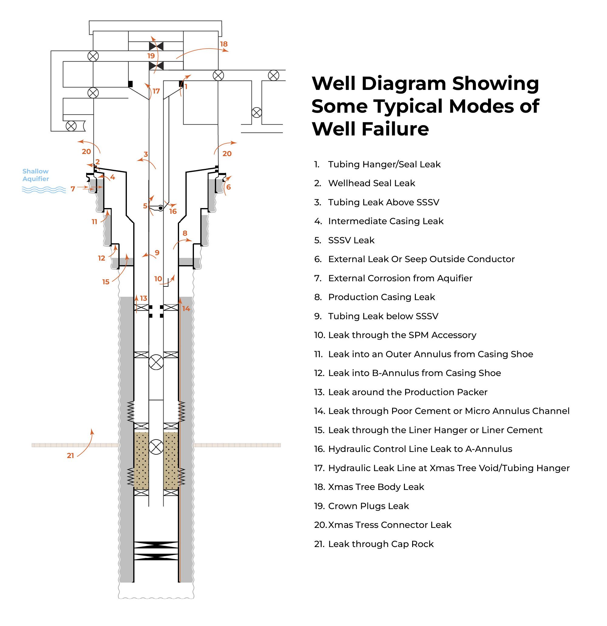
Well barrier elements can experience leak paths due to mechanical stresses, temperature changes, and exposure to corrosive substances. The figure below shows some of the potential leak paths in WBEs.
Here are some strategies for mitigating risks to well barrier integrity:
International industry associations and standardization organizations have issued the following standards, guidelines, and recommended practices related to well integrity.
API STD 53, 4th Edition, Jan 2012
“Blowout Prevention Equipment System for Drilling” is a standard that provides requirements for the installation and testing of blowout prevention (BOP) equipment systems on land and marine drilling rigs.
API RP 96, 1st Edition, Jan 2013
“Deepwater Well Design and Construction” is a recommended practice (RP) that aims to improve safety and reduce the chance of losing well control or damaging the environment. It includes considerations for barrier and load cases. This RP is based on the complexity of deepwater operations, which requires a thorough understanding of well design criteria and the equipment associated with them.
NORSOK D-010 Revs 4, Jun 2013
“Guidelines for Well Integrity in Drilling Well Operations” is the Norwegian oil and gas (O&G) industry standard that defines the minimum functional and performance requirements for well barriers throughout a well’s lifecycle. The standard focuses on how to conduct operations and what equipment should be used and is concerned with drilling, completion, and abandonment activities.
ISO/DIS 16530-1, 2017
“Well Integrity – Lifecycle governance” offers guidance to well operators on managing well integrity throughout the well’s lifecycle. It is intended for use in the petroleum and natural gas industries worldwide and applies to all wells regardless of their age, location, or type. This part of ISO 16530 addresses the minimum compliance requirements for well operators to claim conformity with this part of ISO 16530. The document addresses each stage of the well lifecycle, as defined by six phases: the basis of design, design, construction, operation, intervention, and abandonment.
Wellbore schematics and well barrier diagrams are two distinct methods of illustrating WBEs and their role in integrity management. Each method has its specific applications, contributing to a comprehensive understanding of well integrity management strategies.
A well schematic is an illustration that shows the arrangement of the main WBEs within the well system. The schematic typically includes well and location information, annotations that describe the lithology, depths of the casing and cement sections, descriptions of the major WBEs, mud weights, and formation temperatures.
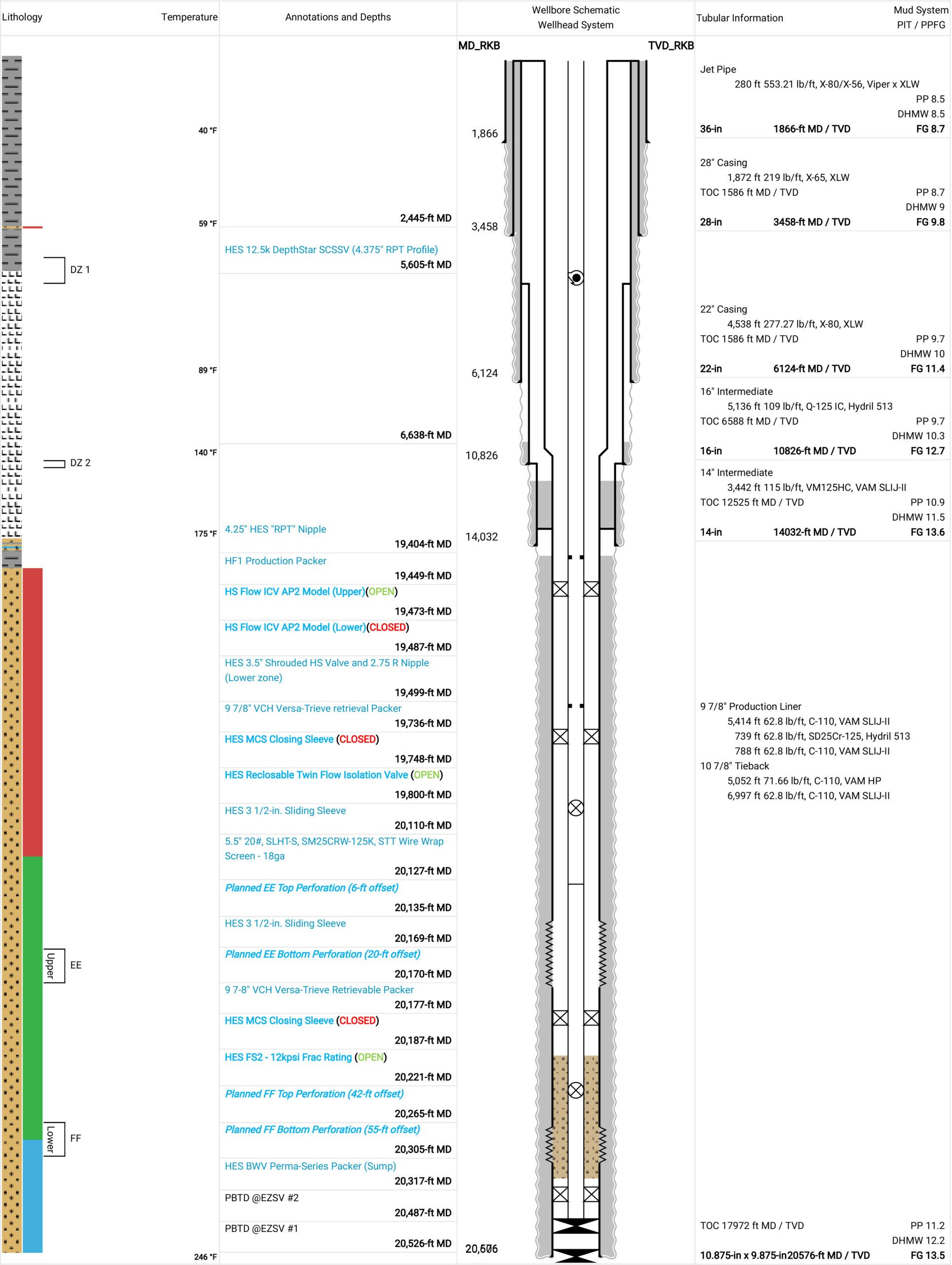
For years, engineers have used various applications to create well schematics, including spreadsheets, word processors, CAD programs, and other planning tools. This has resulted in duplicate data entry with increased potential for errors, change management challenges, and communication and workflow issues during handovers between well phases. Digital well schematic software like IPT Global’s SureTec® WellSchematic allows engineers to build well schematics with barrier diagrams in a centralized Cloud-based repository that tracks the location and information about each WBE in every well.
IPT Global’s digital WellSchematic solution provides several benefits:
Well barrier diagrams display color-coded primary and secondary barrier envelopes and may illustrate all potential leak paths from the reservoir to the surrounding environment. These diagrams describe the status of barrier elements and are valuable for evaluating the consequences and likelihood of specific scenarios. Well barrier diagrams quantify the likelihood of consequences depicted in the diagram, making them useful for risk assessment and decision-making.
Digital well barrier diagram technologies like IPT Global’s WellSchematic BarrierManagement module provide some of the same benefits as digital wellbore schematics, plus:
The development of well integrity software applications and associated technologies has accelerated since 2010, with the increased digitization of the O&G industry after several catastrophic incidents.
Well integrity software applications define the commitments, requirements, and responsibilities of an organization to ensure the integrity and safety of oil and gas wells throughout their lifecycle. The primary aim is to mitigate the risks associated with uncontrolled releases of formation fluids, which can lead to environmental harm, injuries, and financial losses. This is achieved by identifying potential integrity threats, implementing preventive measures, and regularly monitoring well conditions to prevent leaks or failures.
IPT Global offers rigorous well integrity software through its SureTec platform, as well as expert advisory services for advanced well integrity management at every stage of the well lifecycle. SureTec includes solutions for constructing detailed wellbore schematics, the foundation for barrier schematics and test plans. These generate comprehensive test plan reports documenting every surface and subsea WBE to be tested. IPT Global’s integrity tests leverage proprietary algorithms that significantly reduce pressurized time for testing WBEs and remove validation subjectivity, saving rig time and reducing risk. Additionally, IPT Global’s well assurance solutions allow collaboration and handover among teams, while tracking all changes and maintaining versions over the complete lifecycle of wells. Moreover, our expert advisors are available to support the process wherever required, whether onsite or remotely. With decades of experience, they excel in generating and optimizing integrity test plans while offering expert assistance before, during, and after testing operations, regardless of geographic location.
Well barrier envelopes only stay reliable when the people managing them can see what’s actually in the well and confirm those barriers are working as intended. SureTec WellSchematic gives operators that visibility, from the wellbore diagram itself through the barrier plans built in BarrierManagement, so nothing gets tracked in scattered spreadsheets or outdated files. Ready to see how it works for your wells? Contact IPT Global today.
A wellbore diagram, or well schematic, provides a visual representation of the well and its components at any phase of the well lifecycle. It can also serve as a valuable tool to aid in the planning and execution of well operations, from drilling and completions to interventions and abandonment.
The detailed graphical information in wellbore schematics display the size (diameter) and length of major components and the depth at which the components are located.
Wellbore diagrams are a critical communication tool for all stakeholders and decision makers. Wellbore diagram programs should have key features like version control and collaboration capabilities to effectively handle risk management and change control. Wellbore schematics also need to be dynamic to track changes over the lifecycle of the well so that data is up-to-date and available on demand. IPT Global’s SureTec® WellSchematic solution is built around these needs, keeping schematics current and accessible across global operations teams.
The importance of wellbore diagrams cannot be overstated. Over the lifecycle of a well, wellbore diagrams are used for:
In the planning phase, operators and engineers utilize wellbore schematics to visualize design alternatives for the intended well. This aids in the safe and efficient delivery of both the well and the associated business objectives.
When integrated with drilling data acquisition software, wellbore diagrams can be used to communicate operational progress against the plan.
A wellbore diagram assists engineers in overseeing well barriers and assessing risks, as well as making informed decisions regarding the final positioning of casing strings, production tubing, and other completions equipment. It also influences decisions about future completions opportunities.
Coupled with actual well performance and production rate data, wellbore diagrams can help identify potential production challenges and risks associated with well integrity issues.
Frequently updated wellbore diagrams streamline the decision-making process for well interventions and maintenance, serving as a valuable risk management tool to effectively handle well barrier management for interventions.
As a well reaches the end of its lifecycle, wellbore diagrams play a pivotal role in guiding the placement of cement plugs and other well barriers, ensuring the effective prevention of leaks and environmental contamination. This compliance with policy and regulatory requirements is essential, especially during the well abandonment or plug and abandonment process.
Wellbore diagrams differ in appearance but typically contain these components and symbols.
| Component | Description / Symbol |
|---|---|
| General information | Operator, lease name, well number, rig name, legal location, API number, latitude and longitude, date updated |
| Symbol: Displayed at top of schematic | |
| Elevation | Rotary Kelly Bushing (RKB), Mudline (ML), water depth |
| Symbol: Elevation value located at top of the schematic | |
| TD & PBTD | Total Depth of hole and Plugged Back Total Depth |
| Symbol: Values displayed at bottom of schematic | |
| Hole sections | Diameter, top of measured depth, and measured depth |
| Symbol: Vertical or horizontal dashed lines | |
| Casing | Size, weight, top measured depth (TMD), bottom measured depth (BMD), top of cement (TOC) |
| Symbol: Vertical lines representing different casing strings in the wellbore | |
| Cement | Top and bottom of cement, type of cement, yield, and slurry weight |
| Symbol: A shaded area around the casing strings indicating the extent of cement placement | |
| Wellbore components | Packers, plugs, valves, tubing, and gas mandrels |
| Symbol: A rectangle across the wellbore placed at a specific depth | |
| Completion components | Tubing hangers, gauges, production tubing, downhole safety valve, side pocket mandrel, slotted liner, landing nipple, etc. |
| Perforation depth | The location of perforations as defined by top measured depth (TMD) and bottom measured depth (BMD) |
| Symbol: Small, vertically aligned dots or short lines along the casing or tubing | |
| Liner | Size, weight, top measured depth (TMD), bottom measured depth (BMD), top of cement (TOC) |
| Symbol: Vertical lines inside the casing but not extending to the surface | |
| Lithology column | Vertical representation of formations encountered as the well is drilled |
| Symbol: Shading or patterns that distinguish one formation from another | |
| Formation tops | The upper boundary of geological formations |
| Symbol: A horizontal line with the name of the formation indicates the top boundary of a specific geological layer | |
| Geological symbols | Marks that represent geological features such as faults, unconformities, anticlines, and synclines |
| Symbol: A jagged or wavy line intersecting the wellbore trajectory | |
| Drilling fluid | Mud density, viscosity, formation pressures, temperature, etc. |
| Perforations | Top, bottom, shots per foot, and phasing angle |
| Symbol: open (green) and squeezed (red) | |
| Wellbore trajectory | Wellbore path from surface to target depth expressed in terms of measured depth, inclination, and azimuth angles |
| Symbol: An arrow or curve along the wellbore trajectory shows the direction and angle of deviation during directional drilling |
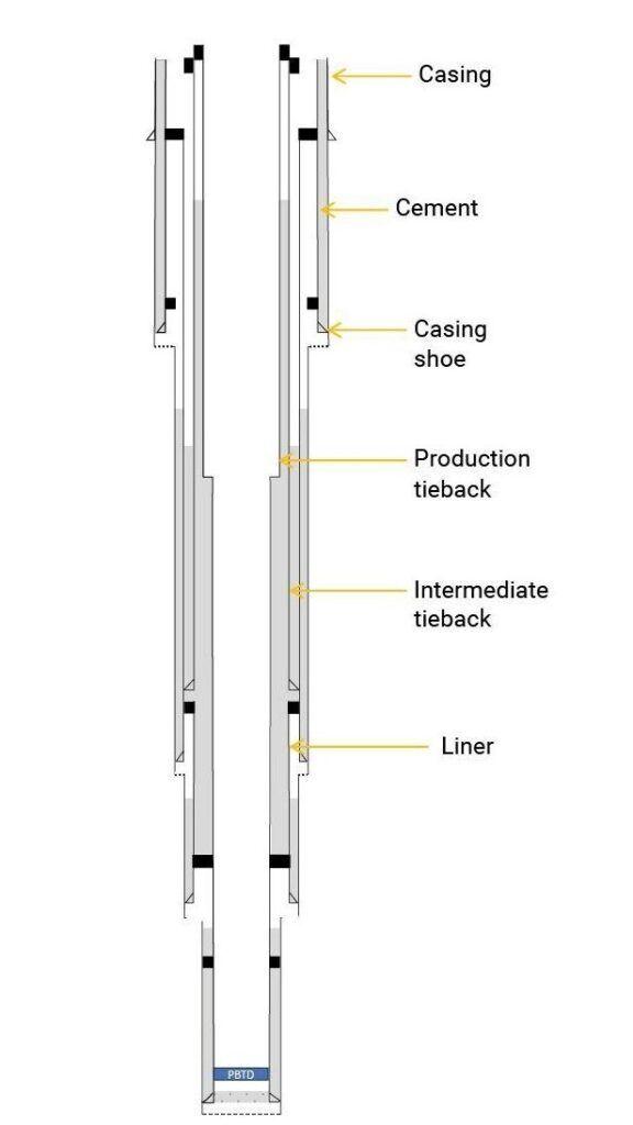
Casing provides structural support to the well and acts as a physical barrier to prevent fluid migration. The casing string consists of casing sections that decrease in diameter with depth. Casing setting points are adjusted to specific depths, for a particular hole diameter. The casing string is run into the wellbore and cemented into place to ensure proper zonal isolation and guarantee impermeable barrier between different formation zones. Casing is often represented in wellbore diagrams using vertical lines to denote different casing sections from the wellhead to the casing shoe. Liners are casing strings that normally run and set within the wellbore and typically do not extend all the way to the wellhead.
Cement is used to create a barrier between the wellbore and the surrounding rock formations. During well construction, the annular space between the casing and the formation is filled with cement. The cement sheath forms a mechanical and hydraulic barrier, preventing fluid migration along the outside of the casing. Cement is depicted in wellbore diagrams by shaded areas that correspond to the depth range where the cement is placed.
A production tieback is typically connected to the top of the production liner or casing string that runs across the production reservoir interval. The primary purpose of a production tieback is to provide a conduit for the flow of hydrocarbons from the reservoir to the surface.
An intermediate tieback is used to isolate a casing string that cannot withstand possible pressure loads during drilling, usually because of excessive wear or higher-than-anticipated pressures. In some cases, intermediate tiebacks may not connect directly to the top of a liner. Instead, they are typically set at a shallower depth and cemented separately from the production liner.
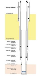
Subsurface formation boundaries and geological features can be accurately represented in wellbore diagrams to clearly indicate the geological formations encountered at various depths or hole sections. This helps drilling teams understand the lithology and potential reservoir characteristics.
Formations are separated by upper and lower boundaries where the rock lithology changes. Subsurface formation data, such as seismic surveys, core samples, and well logs help geologists, drilling engineers, and reservoir engineers accurately place the wellbore in the most favorable locations to optimize drilling efficiency, minimize drilling risks, and optimize future production.
Formation tops represent the upper boundaries of specific geological formation classifications, such as chalk, limestone, shale, and sandstone. They are typically marked with horizontal lines or notches on the lithology column. Formation tops are labeled with the names of the formations they represent and provide valuable information about the depth at which the different formations are encountered.
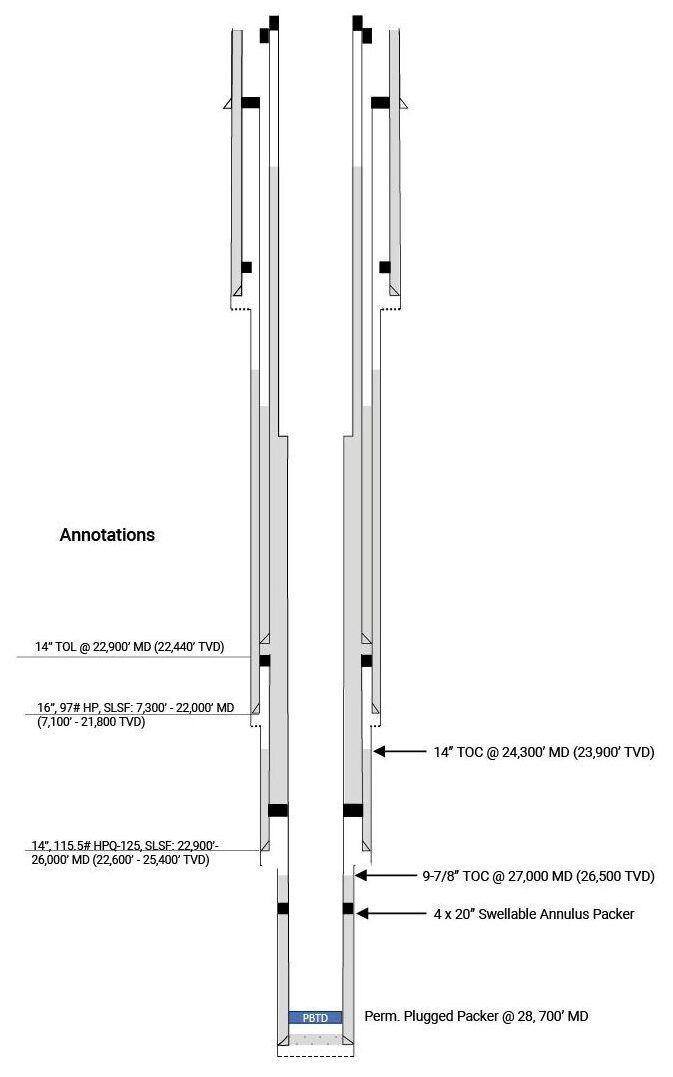
Annotations and labels provide additional information about the formations, features, and wellbore components. They can explain lithology and provide context for significant geological events, seismic characteristics, and more details about wellbore components.
A completions wellbore diagram is a visual representation of the components and configuration of the completions equipment within an oil or gas well. It provides a clear and comprehensive overview of how the well is equipped for production, including the arrangement of tubing, casing, packers, and other wellbore elements. It also serves as a detailed record of the completions design and completions equipment (jewelries) configuration for future reference, maintenance, and regulatory compliance.
The completions diagram is typically accompanied by detailed annotations, specifications, and a legend to explain the symbols and components used. It serves as a critical reference document for well operators, production engineers, and maintenance teams throughout the well’s lifecycle.
IPT Global’s WellSchematic solution and other software used to create wellbore schematics typically contain a range of features and functionalities designed to provide a comprehensive and detailed representation of the wellbore.
| Feature | Description |
|---|---|
| Wellbore visualization | Visual display of the wellbore |
| Casing and tubing strings | Generate casing and tubing sections of different sizes (diameter and thickness), depth, and cement sections |
| Deviations and doglegs | Ability to show any deviations or changes in trajectory during drilling |
| Formation tops | Geological data that indicate the depths of different formation tops encountered during drilling |
| Data integration | Integrates real-time data from drilling operations such as weight on bit (WOB), rate of penetration (ROP), and rotary speed |
| Completion equipment | Production tubing, packers, plugs, and downhole valves |
| Easy editing | Allows users to modify the wellbore path and components |
| Scale and measurements | Tools to measure and modify distances in angles on the wellbore diagram |
| Survey data | Measure depth, inclination, azimuth, vertical section, northing, easting, and readings at various depths |
| Exporting and reporting | Exporting the wellbore diagram in various formats for sharing with colleagues, regulatory authorities, or reports |
| Historical equipment tracking | Records changes to the well’s completion equipment over time |
| Version control | Documenting modifications to the wellbore as it progresses from drilling, completion and production to intervention and abandonment |
| Geothermal information | Captures Surface Ambient Temperature, Seabed/Mudline Temperature, and Formation Temperatures |
| Formation input / information | Comprises pore pressure data and fracture gradient data |
When using wellbore schematic software, accurate data entry, validation, and quality control are crucial to various aspects of safety, compliance, and overall well integrity. Inaccurate data entry can result in errors in well control decision-making, which increases safety risks to personnel, assets, and the environment. Erroneous data entries might result in redesigns, corrosion, collapses, or obstructions in the wellbore. For well operations that are subject to regulatory oversight, inaccurate wellbore schematics can lead to non-compliance, resulting in fines or other legal consequences. Inaccuracies could also lead to improper placement of critical wellbore elements, compromising the well’s structural integrity and potentially causing leaks or other problems over the life of the well. Using wellbore management diagram software with built-in validation checks and data consistency features can help reduce the risk of errors and assist in diagnostics if integrity or production issues arise.
As a well progresses from planning to drilling, completion, production, and abandonment, various wellbore modifications occur. It’s important to keep the wellbore diagram schematic up to date to reflect the specific state and configuration of the well at a given point in time, as well as store all changes that have taken place. Version control is fundamental to change-management processes.
Version control, or versioning, is the practice of documenting changes to wellbore diagrams over a well’s lifecycle to accurately reflect modifications during drilling, completion, workovers, interventions, and abandonment. Each version of the wellbore diagram reflects the specific state and configuration of the well at a given point in time, carrying significant implications for decision-making, regulatory adherence, troubleshooting, and collaboration. This becomes particularly crucial as the responsibility for the well transitions from one department to another throughout its lifespan. Incorporating well-defined approval signatories and technical authorities into the process is an essential requirement for ensuring well integrity.
Wellbore diagram applications have different forms of version control with the goal of a single source of truth. Some applications have project management features that enable users to track versions of wellbore diagrams, while other applications may simply record edits and modifications made to a wellbore diagram. Other applications not only store previous wellbore diagram versions but also alert all relevant users when changes are made to a wellbore diagram so they can update it in their local repository.
Wellbore diagrams are indispensable tools in the oil and gas industry, contributing to the efficient and safe operation of wells. Their role in visualizing, documenting, and communicating wellbore information underscores their importance in every aspect of well management. To ensure successful well operations, it is crucial to adopt wellbore diagram software that makes creating wellbore schematics easy and maintains data accuracy and version control.
To learn how IPT Global’s WellSchematic solution—with barrier diagrams—can support your wellbore schematic needs, contact us today.
Well integrity is crucial to the safety and success of plug and abandonment (P&A) operations, including well decommissioning. P&A operations involve the installation of barriers to seal the wellbore and prevent migration and leakage of formation fluids in perpetuity. Well barrier failure during the decommissioning process could lead to environmental damage, harm to local communities, and significant legal and financial consequences for the operator. This article describes the importance of well integrity in offshore P&A operations and how to assure well integrity through testing and verification of complete barrier systems.
Operators plug and abandon (P&A) a well when it is no longer profitable to produce or useful, as with an injection well. The primary objective of the P&A process is to ensure the well’s integrity by creating a permanent barrier system that isolates the wellbore from the formation and prevents fluid migration into groundwater zones or to the surface.
The P&A process begins with assessing the history and condition of the existing well barrier elements and developing a plan to install and verify additional barriers that are required. IPT Global’s SureTec® WellSchematic solution gives operators a single visual record of the well’s casing, cement, and barrier history, making that initial assessment faster and less dependent on scattered paper files or legacy records. The operator confirms that the plan meets regulatory requirements and industry guidelines and selects a P&A service provider to perform the P&A operations. Once on site, the service provider removes any wellbore debris or obstructions from the wellbore before logging the well to assess its condition and identify any potential subsurface leaks or hazards.
The service provider places cement and mechanical barriers, such as bridge plugs and cement retainers, at predetermined intervals to isolate zones and prevent fluid migration from the formation. A common well abandonment technique is to place cement plugs on top of mechanical plugs. Cement barriers also provide structural support for the casing, prevent corrosion, and structurally reinforce the wellbore. Cement plugs are used in open hole applications and across liner tops. Physical depth tagging may be performed to confirm plug location.
Next, the service provider verifies the integrity of the barriers using pressure testing and cement bond logging. The contractor may also use diagnostic tools, such as temperature surveys and noise logging, to detect any potential channels or leaks in the cement barriers. After verifying barrier integrity, the contractor cuts and removes the wellhead and any remaining wellbore components like production tubing and casing, in accordance with company policy and local regulations. The contractor also retrieves any equipment from the seabed, such as production trees and control systems, and clears the site. Finally, the service provider compiles all documentation of P&A activities into a report for handover to the operator.
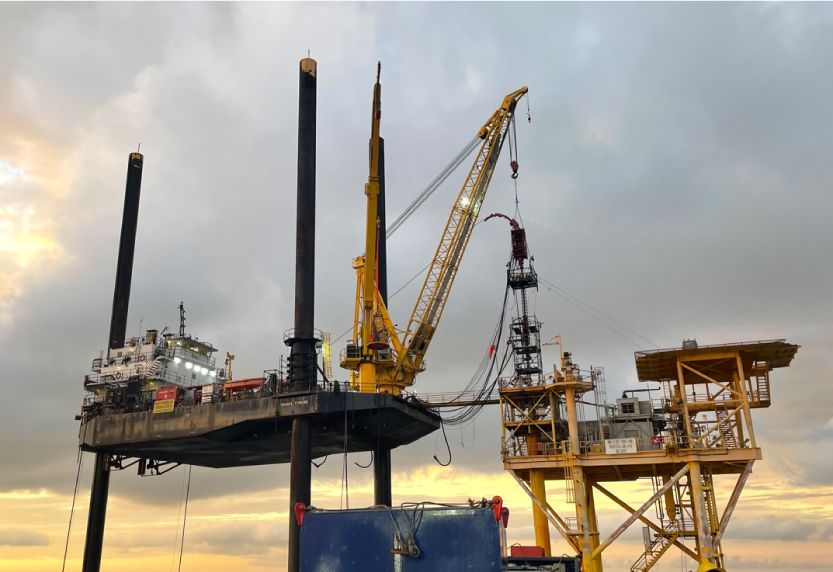
Well integrity is critical to P&A operations regarding regulatory compliance, safety, and environmental considerations. Operators must adhere to regulatory requirements and industry standards to ensure well integrity, and they must use responsible practices to mitigate potential hazards that threaten health, safety, and the environment.

All regulatory agencies require integrity testing of well barrier components. For example, in the United States, the Bureau of Safety and Environmental Enforcement (BSEE) and the Environmental Protection Agency (EPA) provide regulations and guidelines for P&A operations. In the Norwegian petroleum industry, the NORSOK D-010 standard defines the minimal functional requirements for well design, planning, and execution with the aim of maintaining well integrity throughout the lifecycle of the well. In the UK, the North Sea Transition Authority (NSTA) and Health and Safety Executive (HSE) regulate these activities.
Meeting regulatory requirements and obtaining the necessary permits for P&A activities can be challenging, as regulations may differ across jurisdictions and evolve over time. Operators must obtain necessary permits and engage with regulatory authorities throughout the P&A process. This will ensure compliance, reduce risks, and manage changes to approved programs that may be necessary during operations.

Plugged and abandoned wells with compromised well integrity can expose the environment to a variety of air and water pollutants. The release of gases, volatile organic compounds (VOCs), or hazardous air pollutants can occur if proper controls are not implemented during and after P&A operations. The migration of formation fluids into groundwater, surface water bodies, or marine environments may impact water quality and disrupt terrestrial and marine ecosystems. Fluid migration across ineffective barriers may create future operational challenges by creating shallow gas or over-pressured zones at unexpected depths.
Well integrity ensures that the paths between different subsurface formations are sealed so that fluids and gases remain confined within their original formation zones. This prevents the risk of uncontrolled fluid migration that could contaminate soil, groundwater, surface water, or marine environments. A quality program and supporting integrity documentation can demonstrate the effective P&A of assets and may be useful in any investigation or troubleshooting later.
The following is a summary of best practices for ensuring well integrity during and after P&A operations.
Planning P&A activities during the well design phase identifies cost-effective solutions based on well complexity and facilitates smoother execution with a pre-defined plan for abandonment. Early planning also enables knowledge transfer and the handover of critical documentation.
Assess the condition of the well and thoroughly clean the wellbore to remove any obstructions that can interfere with the cement bond integrity and other plugging operations.
Adhere to applicable regulations and guidelines, obtain necessary permits, and engage with regulatory authorities throughout the P&A process to ensure compliance and reduce risks.
Developing well abandonment plans that consider the specific characteristics of the well, reservoir, and surrounding formations is crucial for selecting appropriate techniques and materials to achieve long-term well integrity.
Additional mechanical barriers, such as bridge plugs or cement squeeze operations, may be installed above or below the primary cement barrier to enhance well integrity. All plug depths should be set for the purpose of isolating a zone or protecting a zone based on well conditions and geometry.
Implement rigorous quality control measures, including cement bond logs and pressure testing, to independently test and verify barrier integrity (described in the following section).
Compile reports of all activities, including well logs, pressure test results, cement bond logs, and other relevant data.
Regularly monitor and observe abandoned wells to detect any signs of potential leakage or integrity failure to enable timely remediation actions.
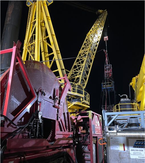
The consequences of a barrier integrity failure are considerable, impacting public health, safety, and the environment, and it can lead to legal and financial penalties and damage to reputation. The integrity of a barrier is not assured until it has been tested and verified using the technologies described below.
Well integrity is not established by individual barrier components but on the collective performance of all components in the wellbore. The operator may use data collected during well construction or run a new cement bond log using a sonic tool that measures the bond quality of the cement to the casing and to the formation. This provides insights into channels or voids in the cement sheath that can act as potential pathways for fluid migration. This information is vital in targeting specific zones for placement of cement plugs and mechanical barriers. Mapping those results against the well’s existing barrier layout in IPT Global’s WellSchematic helps operators confirm exactly where new plugs need to go relative to what’s already in the wellbore. A common abandonment technique is to place a cement plug on top of a mechanical plug at multiple zones in the wellbore. Cement plugs are also used in open hole applications and across liner tops.
All local regulations require cement barriers to extend across the full cross section of the wellbore. The best methods to validate a cement plug placement are the drill pipe weight test and pressure testing. The main advantage of the drill pipe weight test is that it is used to tag the top of the cement in wells with high angles or poor hole conditions to confirm that the plug is at the required depth. However, the weight test is less stringent than pressure testing when measuring the cement plug seal effectiveness.
Pressure testing is the most effective method of barrier verification. It is used to verify the integrity and effectiveness of the collective barrier system based on specific criteria specified by the operator. Pressure testing is also typically performed on a cement plug set above a plug that was tagged. A predetermined pressure is applied that exceeds the anticipated pressure differentials that the barriers are expected to encounter. Positive or negative pressure (inflow) tests are used based on the direction of expected flow. The pressure is analyzed for a specific duration against the operator’s criteria to objectively determine if the barrier system passes or fails.
IPT Global’s SureTec PressureTesting solution provides a comprehensive digital solution for planning, testing, and reporting integrity tests on well barrier systems during P&A operations. Digital pressure testing allows more efficient and accurate integrity assurance because it uses objective criteria to determine whether a pressure test passes or fails.
Qualified professionals should be engaged to carry out monitoring and inspections to properly assess the condition of P&A wells. These professionals should have experience in well integrity management, regulatory requirements, and be able to interpret inspection results accurately.
IPT Global’s subject matter experts provide barrier integrity verification, tracking, and consultation services to support your well assurance program.
The specific steps and techniques to maintain well integrity vary but the means to assure the integrity of the well are constant. IPT Global’s PressureTesting solution tests and verifies the integrity of the entire well barrier system during all phases in the lifecycle of a well, including P&A. Contact us to learn how IPT Global’s WellSchematic and PressureTesting solutions support the success of your P&A operations.
Well integrity is determined by the reliability of well barrier elements (WBEs) to prevent the uncontrolled release of fluids from an oil and gas (O&G) well into the environment. The consequences of the loss of well barrier integrity can be severe, ranging from environmental damage to fatalities. Sustaining well integrity throughout a well lifecycle is critical in minimizing risk due to failed WBEs.
However, a well’s operating conditions or utilization may change as the well ages, adversely affecting the integrity of critical WBEs. It’s difficult to maintain consistency in well integrity over the years through knowledge transfer and documentation handover among teams. To close that gap, IPT Global provides a centralized Cloud-based platform, SureTec®, that manages well integrity data and regulatory compliance through each phase of a well’s life, from drilling, completion, and production to workover, intervention, and plug and abandonment (P&A).
During drilling and completion, the SureTec platform supports well integrity management by bringing barrier verification design, planning, testing, and reporting into one integrated system across the well lifecycle.
Operators use the SureTec WellSchematic solution to build wellbore schematics and barrier diagrams, and the SureTec PressureTesting TestPlanner module to build test plans for drilling and completion. Together, they generate a standardized, detailed test plan report with schematics, criteria, and complete documentation of surface and subsea components to be tested. The tests plans can be digitally routed for approval and securely stored in SureTec’s Cloud-based platform.
IPT Global’s SureTec allows signatories to download and review drilling and completion test plan reports, and it simplifies the gathering of digital approvals via mobile devices. It streamlines collaboration and communication by rerouting rejected test plans and test reports for modifications and final approval.
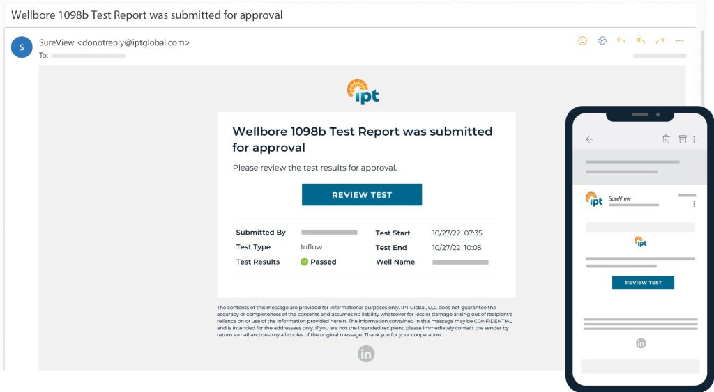
Performing accurate, comprehensive, and efficient integrity tests during drilling and completion is a challenge in high-pressure, high-temperature (HPHT) environments. It requires comprehensive well integrity management software and effective collaboration between the operator and service company performing the tests. An accurate, consistent, and transparent methodology is necessary for validating and managing the integrity of WBEs. IPT Global’s patented, physics-based algorithms evaluate pressure test data based on objective criteria and definitively confirm whether an integrity test passed or failed. Reports for completed tests are automatically uploaded to the Cloud and routed for digital approval using SureTec PressureTesting’s DigitalApprovals module. Likewise, PressureTesting’s RemoteView module provides remote viewing of active tests from anywhere in the world, test data archival and retrieval, and advanced data visualization analysis.
IPT Global’s industry-leading experts collaborate with operators and drilling contractors both on-site and remotely through its Real-time Operations Center (RTOC). Field Service Advisors provide on-site integrity test coordination and optimization, Engineers perform post-test reviews to ensure all components are properly tested, Real-Time Operations Engineers & Advisors (RTOAs) verify that test reports are published properly to assure the traceability of all integrity tests for hand-off to the production team, and BOP Compliance Surveyors provide third-party equipment inspection and auditing using industry recommended survey and inspection practices.
Blowout preventers (BOPs) serve as a critical secondary barrier during drilling. The challenge for drilling contractors and operators is to know when to repair or replace BOP components to minimize non-productive time (NPT) due to component malfunction or failure. Regulations require operators to periodically pressure test and function test BOP stack components to ensure well integrity. Contractors perform weekly function tests to actuate the rams and annular preventers to ensure they will operate properly in an emergency. The actuation duration and volume of hydraulic fluid required are important indicators of the health of critical BOP components.
IPT Global engineers monitor and analyze BOP pressure tests, BOP function tests, maintenance, and failure data to gain insight into when and why failures occur. Engineers use data visualization to spot trends in pressure and function test data so that contractors can repair and replace BOP components, when necessary, rather than on an arbitrary schedule as commonly used.
During the production phase of the well lifecycle, there are a different set of challenges to maintaining integrity while optimizing production. These challenges include complex physical and chemical process changes that occur in the wellbore and surrounding formations. Adding to this complexity, aging oil and gas wells become more prone to corrosion, erosion, and other forms of wear and tear that can compromise well integrity. The production team must decide when to intervene and extend production or retire a well that is no longer safe or economically viable.
IPT Global’s SureTec solution ensures complete documentation handover to the production team. It gives the team access to WBE integrity data and reports for transparency and compliance. It also allows the team to compare integrity data with other wells to identify potential issues before they become major problems.
Integrity testing of well components during light and heavy (workover) interventions presents different challenges compared to testing during well construction. As interventions have a shorter duration of a few weeks, component integrity tests are carried out more frequently compared to the construction of a well. Many offline integrity tests are performed simultaneously on the deck of the intervention vessel to eliminate delays once the crew connects to the well.
Multi-testing capability enables the crew to perform integrity tests thoroughly and efficiently to avoid delays in critical path operations that would be costly for both the intervention service company and the operator. After the intervention is completed, there is traceability of all well integrity tests to hand off to the production team and for compliance with local regulatory bodies.
Compliance regulations that govern plug and abandonment (P&A) regulations can vary across jurisdictions, which makes compliance challenging for operators with international assets. Operators must comply with these regulations to ensure safe and environmentally responsible operations. Regulations typically cover a range of areas, such as casing and cementing requirements, pressure testing procedures, and monitoring and reporting requirements.
A critical aspect of compliance with P&A regulations is the need for integrity management of well barrier elements (WBE). Well integrity management software like SureTec can be used to provide historical data on each WBE. This data can help operators identify potential issues that may arise during the abandonment process, such as defective equipment or oil leaks. All P&A activities can be tracked and documented, providing a comprehensive record of the operation ensuring compliance with regulations are met. With this data, operators can take steps to ensure the well is abandoned safely and mitigate risks.
Ensure the reliability of well barrier elements over the entire well lifecycle. Implement IPT Global’s SureTec platform to manage well integrity data, regulatory compliance, and integrity testing through each phase of the well’s life. With WellSchematic and PressureTesting, you can strengthen well integrity management during drilling and completion, maintain BOP integrity, and support production and P&A compliance.
Contact us to learn how IPT Global can help you manage well integrity throughout the well lifecycle.
IPT Global’s expert advisory services and SureTec® PressureTesting software solution came together to deliver value to all stakeholders during a well intervention program in Angola, off the west coast of Southern Africa. An intervention services company (ISC) took on an extensive program, with the goal of having its own personnel perform the integrity tests while relying on remote support from IPT Global, including our Field Advisors and Real-Time Operations Center (RTOC). The ISC wanted to demonstrate the ability to provide turnkey intervention services for various operators while performing the tests safely and efficiently to avoid costly non-productive time (NPT). IPT Global’s team worked with the ISC to create a custom operational support plan comprising in-house and on-site training, optimization of planning and test execution, and remote support.
IPT Global provided pre-deployment training at its office for the ISC’s engineers and managers. The training focused on using existing test plans to run tests and publish reports. Several variations of the test plans were run using existing schematics. IPT Global provided setup guides for the digital acquisition (DAQ) unit and transducers, along with quick start guides to run various tests in the SureTec platform. The participants were able to experience live data acquisition and testing scenario simulations, allowing them to become familiar with the PressureTesting workflows & procedures.
At the rig site, IPT Global’s Field Advisors trained intervention personnel so they could run SureTec PressureTesting with remote support from our RTOC. The training focused on using PressureTesting’s TestPlanner and TestEngine modules to guide testing efforts, leveraging the RTOC for remote support and publishing tests. IPT Global’s RTOC and engineers helped to manage the testing program with handover and record archival while transitioning between wells.
The operator planned 28 integrity tests, with specific criteria for each of the test types performed. IPT Global engineers created a test matrix for the ISC that included the operator’s criteria and a procedural reference for each test, making review and approval easier. The SureTec TestPlanner matrix also helped ISC personnel manage the testing program by making it easier to locate and run previously built test plans on the testing laptop. This allowed the company to focus on their operations and setting up the hardware rather than having to set up each test plan.
Completed tests and reports were saved in SureTec for archival and traceability. The SureTec Platform is a secure, web-based tool that also provides real-time status of pressure tests, test data organization and retrieval by well and date, advanced data analysis, and remote viewing of active tests.
The ISC received remote support from IPT Global’s RTOC, which is staffed by experienced engineers and advisors who monitor all pressure tests 24/7 and provide global technical support. Remote support ranges from assisting with data connections, networking issues, and basic software issues to advanced support such as:
The intervention program required 28 integrity tests with various operator criteria to be performed over a relatively short period. The ISC successfully executed the intervention program and achieved its primary goal of providing turnkey service with digital software and remote support from IPT Global.
SureTec’s PressureTesting solution provided accuracy, objectivity, and flexibility that assured the integrity of all tested components according to the operator’s criteria. Our engineers performed post-test reviews to ensure all components were tested to the proper pressure as dictated by the operator. And IPT Global field advisors verified that test reports were published properly to assure the traceability of all integrity tests for hand-off to the production team and to provide an auditable trail of compliance for local regulatory bodies.
Most importantly, the ISC was able to deliver the intervention program safely to protect people, the environment, assets, and the reputations of all stakeholders.
To learn more about the SureTec platform and our PressureTesting solution, contact us today.