
A wellbore diagram, or well schematic, provides a visual representation of the well and its components at any phase of the well lifecycle. It can also serve as a valuable tool to aid in the planning and execution of well operations, from drilling and completions to interventions and abandonment.
The detailed graphical information in wellbore schematics display the size (diameter) and length of major components and the depth at which the components are located.
Wellbore diagrams are a critical communication tool for all stakeholders and decision makers. Wellbore diagram programs should have key features like version control and collaboration capabilities to effectively handle risk management and change control. Wellbore schematics also need to be dynamic to track changes over the lifecycle of the well so that data is up-to-date and available on demand. IPT Global’s SureTec® WellSchematic solution is built around these needs, keeping schematics current and accessible across global operations teams.
The importance of wellbore diagrams cannot be overstated. Over the lifecycle of a well, wellbore diagrams are used for:
In the planning phase, operators and engineers utilize wellbore schematics to visualize design alternatives for the intended well. This aids in the safe and efficient delivery of both the well and the associated business objectives.
When integrated with drilling data acquisition software, wellbore diagrams can be used to communicate operational progress against the plan.
A wellbore diagram assists engineers in overseeing well barriers and assessing risks, as well as making informed decisions regarding the final positioning of casing strings, production tubing, and other completions equipment. It also influences decisions about future completions opportunities.
Coupled with actual well performance and production rate data, wellbore diagrams can help to identify potential production challenges and risks associated with well integrity issues.
Frequently updated wellbore diagrams streamline the decision-making process for well interventions and maintenance, serving as a valuable risk management tool to effectively handle well barrier management for interventions.
As a well reaches the end of its lifecycle, wellbore diagrams play a pivotal role in guiding the placement of cement plugs and other well barriers, ensuring the effective prevention of leaks and environmental contamination. This compliance with policy and regulatory requirements is essential, especially during the well abandonment or plug and abandonment process.
Wellbore diagrams differ in appearance but typically contain these components and symbols.
| Component | Description / Symbol |
|---|---|
| General information | Operator, lease name, well number, rig name, legal location, API number, latitude and longitude, date updated |
| Symbol: Displayed at top of schematic | |
| Elevation | Rotary Kelly Bushing (RKB), Mudline (ML), water depth |
| Symbol: Elevation value located at top of the schematic | |
| TD & PBTD | Total Depth of hole and Plugged Back Total Depth |
| Symbol: Values displayed at bottom of schematic | |
| Hole sections | Diameter, top of measured depth, and measured depth |
| Symbol: Vertical or horizontal dashed lines | |
| Casing | Size, weight, top measured depth (TMD), bottom measured depth (BMD), top of cement (TOC) |
| Symbol: Vertical lines representing different casing strings in the wellbore | |
| Cement | Top and bottom of cement, type of cement, yield, and slurry weight |
| Symbol: A shaded area around the casing strings indicating the extent of cement placement | |
| Wellbore components | Packers, plugs, valves, tubing, and gas mandrels |
| Symbol: A rectangle across the wellbore placed at a specific depth | |
| Completion components | Tubing hangers, gauges, production tubing, downhole safety valve, side pocket mandrel, slotted liner, landing nipple, etc. |
| Perforation depth | The location of perforations as defined by top measured depth (TMD) and bottom measured depth (BMD) |
| Symbol: Small, vertically aligned dots or short lines along the casing or tubing | |
| Liner | Size, weight, top measured depth (TMD), bottom measured depth (BMD), top of cement (TOC) |
| Symbol: Vertical lines inside the casing but not extending to the surface | |
| Lithology column | Vertical representation of formations encountered as the well is drilled |
| Symbol: Shading or patterns that distinguish one formation from another | |
| Formation tops | The upper boundary of geological formations |
| Symbol: A horizontal line with the name of the formation indicates the top boundary of a specific geological layer | |
| Geological symbols | Marks that represent geological features such as faults, unconformities, anticlines, and synclines |
| Symbol: A jagged or wavy line intersecting the wellbore trajectory | |
| Drilling fluid | Mud density, viscosity, formation pressures, temperature, etc. |
| Perforations | Top, bottom, shots per foot, and phasing angle |
| Symbol: open (green) and squeezed (red) | |
| Wellbore trajectory | Wellbore path from surface to target depth expressed in terms of measured depth, inclination, and azimuth angles |
| Symbol: An arrow or curve along the wellbore trajectory shows the direction and angle of deviation during directional drilling |
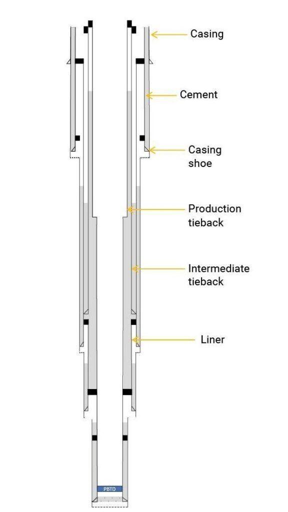
Casing provides structural support to the well and acts as a physical barrier to prevent fluid migration. The casing string consists of casing sections that decrease in diameter with depth. Casing setting points are adjusted to specific depths, for a particular hole diameter. The casing string is run into the wellbore and cemented into place to ensure proper zonal isolation and guarantee impermeable barrier between different formation zones. Casing is often represented in wellbore diagrams using vertical lines to denote different casing sections from the wellhead to the casing shoe. Liners are casing strings that normally run and set within the wellbore and typically do not extend all the way to the wellhead.
Cement is used to create a barrier between the wellbore and the surrounding rock formations. During well construction, the annular space between the casing and the formation is filled with cement. The cement sheath forms a mechanical and hydraulic barrier, preventing fluid migration along the outside of the casing. Cement is depicted in wellbore diagrams by shaded areas that correspond to the depth range where the cement is placed.
A production tieback is typically connected to the top of the production liner or casing string that runs across the production reservoir interval. The primary purpose of a production tieback is to provide a conduit for the flow of hydrocarbons from the reservoir to the surface.
An intermediate tieback is used to isolate a casing string that cannot withstand possible pressure loads during drilling, usually because of excessive wear or higher-than-anticipated pressures. In some cases, intermediate tiebacks may not connect directly to the top of a liner. Instead, they are typically set at a shallower depth and cemented separately from the production liner.
Subsurface formation boundaries and geological features can be accurately represented in wellbore diagrams to clearly indicate the geological formations encountered at various depths or hole sections. This helps drilling teams understand the lithology and potential reservoir characteristics.
Formations are separated by upper and lower boundaries where the rock lithology changes. Subsurface formation data, such as seismic surveys, core samples, and well logs help geologists, drilling engineers, and reservoir engineers accurately place the wellbore in the most favorable locations to optimize drilling efficiency, minimize drilling risks, and optimize future production.
Formation tops represent the upper boundaries of specific geological formation classifications, such as chalk, limestone, shale, and sandstone. They are typically marked with horizontal lines or notches on the lithology column. Formation tops are labeled with the names of the formations they represent and provide valuable information about the depth at which the different formations are encountered.
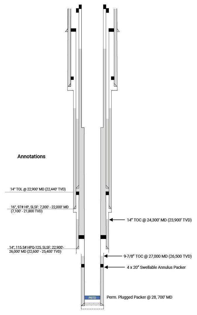
Annotations and labels provide additional information about the formations, features, and wellbore components. They can explain lithology and provide context for significant geological events, seismic characteristics, and more details about wellbore components.
A completions wellbore diagram is a visual representation of the components and configuration of the completions equipment within an oil or gas well. It provides a clear and comprehensive overview of how the well is equipped for production, including the arrangement of tubing, casing, packers, and other wellbore elements. It also serves as a detailed record of the completions design and completions equipment (jewelries) configuration for future reference, maintenance, and regulatory compliance.
The completions diagram is typically accompanied by detailed annotations, specifications, and a legend to explain the symbols and components used. It serves as a critical reference document for well operators, production engineers, and maintenance teams throughout the well’s lifecycle.
IPT Global’s WellSchematic solution and other software used to create wellbore schematics typically contain a range of features and functionalities designed to provide a comprehensive and detailed representation of the wellbore.
| Feature | Description |
|---|---|
| Wellbore visualization | Visual display of the wellbore |
| Casing and tubing strings | Generate casing and tubing sections of different sizes (diameter and thickness), depth, and cement sections |
| Deviations and doglegs | Ability to show any deviations or changes in trajectory during drilling |
| Formation tops | Geological data that indicate the depths of different formation tops encountered during drilling |
| Data integration | Integrates real-time data from drilling operations such as weight on bit (WOB), rate of penetration (ROP), and rotary speed |
| Completion equipment | Production tubing, packers, plugs, and downhole valves |
| Easy editing | Allows users to modify the wellbore path and components |
| Scale and measurements | Tools to measure and modify distances in angles on the wellbore diagram |
| Survey data | Measure depth, inclination, azimuth, vertical section, northing, easting, and readings at various depths |
| Exporting and reporting | Exporting the wellbore diagram in various formats for sharing with colleagues, regulatory authorities, or reports |
| Historical equipment tracking | Records changes to the well’s completion equipment over time |
| Version control | Documenting modifications to the wellbore as it progresses from drilling, completion and production to intervention and abandonment |
| Geothermal information | Captures Surface Ambient Temperature, Seabed/Mudline Temperature, and Formation Temperatures |
| Formation input / information | Comprises pore pressure data and fracture gradient data |
When using wellbore schematic software, accurate data entry, validation, and quality control are crucial to various aspects of safety, compliance, and overall well integrity. Inaccurate data entry can result in errors in well control decision-making, which increases safety risks to personnel, assets, and the environment. Erroneous data entries might result in redesigns, corrosion, collapses, or obstructions in the wellbore. For well operations that are subject to regulatory oversight, inaccurate wellbore schematics can lead to non-compliance, resulting in fines or other legal consequences. Inaccuracies could also lead to improper placement of critical wellbore elements, compromising the well’s structural integrity and potentially causing leaks or other problems over the life of the well. Using wellbore management diagram software with built-in validation checks and data consistency features can help reduce the risk of errors and assist in diagnostics if integrity or production issues arise.
As a well progresses from planning to drilling, completion, production, and abandonment, various wellbore modifications occur. It’s important to keep the wellbore diagram schematic up to date to reflect the specific state and configuration of the well at a given point in time, as well as store all changes that have taken place. Version control is fundamental to change-management processes.
Version control, or versioning, is the practice of documenting changes to wellbore diagrams over a well’s lifecycle to accurately reflect modifications during drilling, completion, workovers, interventions, and abandonment. Each version of the wellbore diagram reflects the specific state and configuration of the well at a given point in time, carrying significant implications for decision-making, regulatory adherence, troubleshooting, and collaboration. This becomes particularly crucial as the responsibility for the well transitions from one department to another throughout its lifespan. Incorporating well-defined approval signatories and technical authorities into the process is an essential requirement for ensuring well integrity.
Wellbore diagram applications have different forms of version control with the goal of a single source of truth. Some applications have project management features that enable users to track versions of wellbore diagrams while other applications may simply record edits and modifications made to a wellbore diagram. Other applications not only store previous wellbore diagram versions but also alert all relevant users when changes are made to a wellbore diagram so they can update it in their local repository.
Wellbore diagrams are indispensable tools in the oil and gas industry, contributing to the efficient and safe operation of wells. Their role in visualizing, documenting, and communicating wellbore information underscores their importance in every aspect of well management. To ensure successful well operations, it is crucial to adopt wellbore diagram software that makes creating wellbore schematics easy and maintains data accuracy and version control.
To learn how IPT Global’s WellSchematic solution—with barrier diagrams—can support your wellbore schematic needs, contact us today.
IPT Global’s SureTec® platform ties well integrity management together with WellSchematic, PressureTesting, and Equipment Health Monitoring in one web-based, mobile-friendly solution. The platform gathers and manages data across IPT Global’s solutions and displays it in specialized views that support testing and monitoring activities. From designing test plans and monitoring blowout preventer (BOP) performance to streamlining collaboration and identifying performance improvement opportunities, SureTec enables team members around the world to securely view and manage operations in real time.
The SureTec platform connects well design, barrier management, pressure testing, equipment health monitoring, and compliance activities into a continuous assurance workflow. Information flows between disciplines, giving teams a shared view of the well and reducing manual handoffs across the lifecycle. SureTec monitors, archives, and inspects the results of wellbore element (WBE) tests. Clients can review specific details of each test and identify opportunities to drive performance enhancements through KPIs that are created for tests and rig operations. The PressureTest Module seamlessly integrates with BOP and Well Control Equipment Schematics, Wellbore diagrams, barrier plans, and equipment health status.
Through PressureTesting’s RemoteView module, clients can monitor real-time pressure activities from anywhere on any device. If a problem or failure occurs, that real-time monitoring capability reduces communication lag and improves troubleshooting through collaboration.
The SureTec platform also includes IPT Global’s Equipment Health Monitoring solution, which provides live monitoring dashboards, event and alarm monitoring, and historical data retrieval to support BOP reliability throughout all phases of BOP operations. Alongside the rest of IPT Global’s ecosystem, it supports compliance for 21-day testing in the Gulf of America and our condition-based monitoring initiative.
SureTec’s approval workflow feature manages plan versions and allows clients to review and approve test plans before a test begins. It also supports the review and approval of test results upon successful completion. Clients can approve or request changes to a test plan or completed report, and an email alerts users when updates are needed. An audit log of all approved plans, tests, and approval activity is maintained for accurate record keeping and compliance.
The SureTec platform also integrates with data lakes and verification management systems through secure, industry-standard interfaces, automating manual processes and improving data quality.
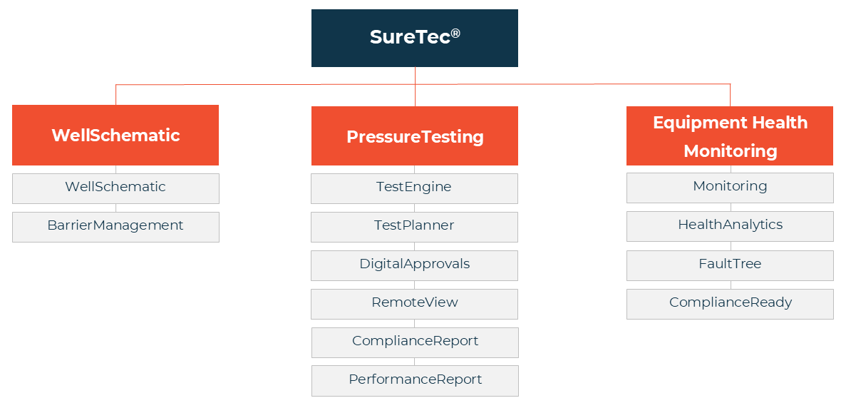
With the SureTec platform, well integrity, testing, and equipment health data all live in one connected ecosystem, so your teams spend less time reconciling records and more time acting on them. Contact us to learn how IPT Global can support your operations.
Integrity management is fundamental to developing and operating a well that safely performs as designed while minimizing risk to personnel, assets, the environment, and reputation. A well without proper integrity management can jeopardize worker safety and the surrounding environment.
In a safety-critical industry like oil and gas, well integrity management is essential. It is the act of achieving assurance through the proper design, construction, testing, and maintenance of the well structure throughout all well operations. A standardized well integrity program ensures processes are defined, consistent, reviewed, and open to improvements.
Most operators have their own standards for well integrity solutions; however, even within a single operator’s own operations, those standards can vary significantly, for example from region to region. When integrity management is not standardized, one rig team may conduct inflow tests using a different approach than another rig team. Workers at one site could utilize a dedicated solution for data management, while those somewhere else may decide Excel is a perfectly acceptable substitute.
Inconsistencies inevitably present challenges, such as deploying effective training programs, best practices, test analysis methods, acceptance criteria determination, and review and approval processes, to name a few. Left unaddressed, these gaps can compromise safety, reliability, and performance.
When standards are implemented and consistently followed, it ensures everyone is looking at the same playbook. This avoids the confusion that comes from multiple job sites each using their own tools and processes. Instead, you establish norms that bring consistency and streamline well integrity management.
Standardization provides confidence that the same workflows are used everywhere. Tests are performed the same way. Maintenance schedules are on the same timeline. Data is stored in the exact same manner. And reports are generated using the same software. The result is a much more consistent approach to well integrity management.
A single standard across all sites enables integration and meaningful data analysis. Cloud-based tools like IPT Global’s SureTec® platform allow you to connect to each location, monitor assets and operations, and access whatever data you might need.
IPT Global’s well integrity solution is comprehensive, spanning the entirety of the well lifecycle. Our SureTec platform, including WellSchematic, PressureTesting, and Equipment Health Monitoring, works alongside our industry experts to bring standardization to processes, workflows, and tools from start to finish. And because our solution is entirely digital, you can easily monitor work or access data from any site, regardless of where you are.
IPT Global helps you simplify well integrity management while also improving safety, reliability, and performance. If you’re looking for a more streamlined and consistent well integrity management program, contact IPT Global today to learn about our standardized and integrated solution.