Exploring Coiled Tubing Operations: Applications, Components, and Best Practices
August 21, 2024
What is Coiled Tubing?
Coiled tubing (CT) is a long, flexible, metal or composite pipe with no joints that is used in the oil and gas industry for a variety of purposes:
Drilling: CT drilling can be faster than conventional drilling because it doesn’t require connections. CT can also enable horizontal drilling, which can maximize well potential by accessing difficult formations.
Production tubing: CT can be used to extract remaining resources from depleted gas wells.
Well interventions: CT can be inserted into wells to clean debris, perform stimulation treatments, and gather data through logging. It can also be used for cementing, acidizing, drilling out frac plugs during hydraulic fracturing, and well control.
Coiled tubing has several advantages, including increased efficiency, cost effectiveness, and safer operations. Some of its disadvantages include limited depth and borehole size, high maintenance costs, and reduced accuracy. This article describes the operation and applications for coiled tubing units (CTUs), and it specifically covers the well control stack and industry recommended practices for pressure testing coiled tubing.
Coiled Tubing Components
Coiled tubing units (CTUs) include the following components:
Coiled tubing – The tubing is typically 1 to 3.25 inches (25–83 mm) in diameter and can range from 2,000 to 15,000 ft (610 to 4,570 m) long, or more.
Coiled tubing reel – The tubing reel is connected to the coiled tubing string and the injector head. It includes high-pressure swivels that allow the reel to rotate while maintaining a secure connection to the tubing and surface equipment. Tubing reels vary in size depending on the specific operation and the diameter of the coiled tubing. Reels can store several thousand feet of coiled tubing. For example, a standard reel might hold between 10,000 and 20,000 feet of 1.5-inch diameter tubing.
Injector head – The injector head uses a set of grippers to feed the coiled tubing in and out of the well while controlling the speed and direction of the tubing for precise control during operations. It supports the weight of the coiled tubing, preventing it from buckling or kinking as it is inserted or withdrawn from the well.
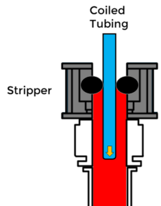
Stripperassembly – The stripper is located below the injector. It contains rubber pack off elements that create a seal around the tubing to isolate the well’s pressure.
Pumping unit – One or more pumps can be used to pump fluid through the tubing to different zones.
Manifold – Typically attached to the reel to allow different pumps and equipment to tie in.
Power pack – Provides hydraulic power to control and operate the CTU and pressure control equipment.
Control cabin – Provides a clear view of all major equipment and is equipped with the instruments and control systems needed to operate the CTU:
Downhole CT connectors and bottom hole assembly (BHA) components – Connect the CT to the BHA, which contains tools and equipment used for downhole operations.
Well control surface stack – The surface stack is designed to manage the unique challenges posed by coiled tubing operations. It ensures well control by sealing around the tubing to control the overflow of oil, gas, and water, thereby preventing blowouts and avoiding resource waste.
Coil Tubing Applications
Coiled Tubing Drilling (CTD)
Coiled tubing can be used for drilling operations without the use of drill pipe and a rotary table, which speeds up the process. A bottom hole assembly (BHA) with a drill bit is connected to the coil tubing and inserted in the well. The injector head pushes the tubing into the well and the BHA uses a motor or rotary steerable system that rotates the drill bit. The BHA is essential for directional drilling and wellbore navigation.
A downhole mud motor may also be used in coiled tubing drilling operations to convert the hydraulic energy of the drilling fluid into mechanical energy to rotate the drill bit independently of the coiled tubing string.
Circulation
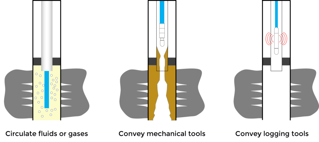
Coiled tubing is a beneficial tool for circulation in well interventions due to its continuous length’s ability to navigate complex wellbores. Most often, the operation will involve pumping nitrogen or various fluids to free the well of light debris (sand) and removing water or condensates built up during production.
Logging
Coiled tubing allows the deployment of logging tools into the wellbore to collect data about the formation and well conditions, such as formation pressure, fluid composition, temperature and formation properties. This is especially useful in highly deviated or horizontal wells where traditional wireline logging might be challenging.
Perforating
Subsea lubricators dictate the length of perforating guns that can be run when using conventional drill pipe. Coiled tubing simplifies perforating operations by allowing the use of long bottom hole assemblies (BHA) while maintaining dual well control barriers. This enhances safety and operational efficiency.
Pumping
Coiled tubing can be connected to pumping units and inserted in a well to pump fluids for various treatments, including well stimulation, hydraulic fracturing, acidizing and cementing. The ability to pump the fluid without interruption while continuously inserting the coiled tubing allows a steady and controlled flow rate.
Production
Coiled tubing can be used for various production enhancement techniques, such as gas lift or artificial lift systems, contributing significantly to improved efficiency and reduced downtime. In gas lift installations, CT enables more efficient and precise placement of gas lift valves along the tubing string, especially in deep or deviated wells. In artificial lift systems, CT significantly reduces installation time for electric submersible pump systems in shallow gas wells to address liquid loading issues.
Intervention
CT is valued for its flexibility, efficiency, and ability to perform a wide range of tasks without the need for a rig, making it an essential tool in offshore well interventions.
CT is used to remove obstructions such as sand, scale, and debris from the wellbore to ensure optimal flow and production.
It is employed for pumping acids or other stimulation fluids directly into the reservoir stimulation to enhance well productivity.
It allows for the circulation of fluids within the wellbore, even when the well is under pressure. This is crucial for various well control operations and to maintain well integrity.
It can deploy logging tools and perforating guns into the wellbore. This enables the acquisition of downhole data and the creation of new perforations to improve well performance.
It can be used to set mechanical barriers or plugs within the wellbore, which is essential for isolating sections of the well during different phases of intervention or production.
Coiled Tubing Operation
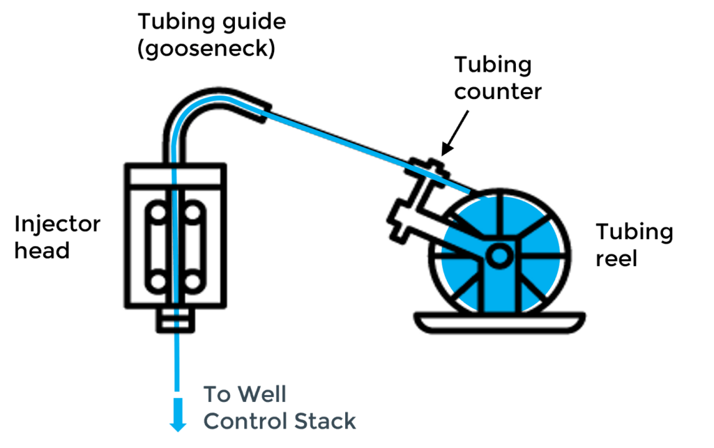
The CT operator in the control cabin manages the entire process of deploying and retrieving the tubing during CT operations. Coiled tubing is spooled off the reel and passes through a tubing counter that measures the length of the tubing being deployed and retrieved. The tubing is then guided through a gooseneck and directed downward to the hydraulically driven injector head, which the CT operator uses to control the movement and depth of the CT string. The tubing becomes straight before it enters the well control surface stack.
Beneath the injector head, the stripper assembly on top of the well control stack provides a dynamic seal around the tubing string, which is crucial for running the CT in and out of live wells.
During intervention operations, CT can be used to circulate acid, nitrogen or cement. Devices may also be conveyed down the tubing for purposes such as sealing, cleaning, or initiating other downhole operations. For example, balls may be pumped down the tubing to isolate sections of the well, or darts may be used to trigger tools and other chemical treatments. The CTU uses hydraulic pressure to push these devices down the tubing and through a dual-flapper check valve. The flow of hydraulic fluid is carefully controlled to ensure the devices travel to reach their target accurately. Coil tubing also allows logging tools to be deployed down the wellbore to collect data about the formation and well conditions. The CT Operator monitors the movement of devices in real time using sensors and telemetry systems.
At the end of the operation, the tubing is pulled out of the well and spooled back onto the reel. A high-pressure swivel joint on the reel hub allows fluid to be pumped while the reel rotates.
Recommended Practices and Standards for Coiled Tubing Operations
Coiled Tubing operations are governed by regulatory standards and recommended practices to ensure safety and efficiency. Key standards and recommended practices are 30 CFR Part 250 Subpart G and API RP 16ST, respectively. 30 CFR Part 250 Subpart G is a mandatory federal regulation for outer continental shelf operations, whereas API RP 16ST is a voluntary industry standard. The recommended practices in API RP 16ST offer detailed guidance to support and enhance compliance with the regulations set forth in 30 CFR part 250 sub part G.
API RP 16ST Coiled Tubing Standards
API RP 16ST (Recommended Practice for Coiled Tubing Well Control Equipment Systems) is a crucial standard governing coiled tubing operations. The second edition, along with its Addendum 1 from February 2022, provides updated guidelines for well control equipment systems used in coiled tubing operations to ensure enhanced safety and operational efficiency. A summary of some of the key sections of the recommended practice are listed below.
Coiled Tubing Well Control Barriers
A coiled tubing (CT) well control barrier is defined as a tested mechanical device, or a combination of devices, designed to prevent the uncontrolled release of wellbore fluids.
Key components include:
Combination components in CT BHA: Pipe ram sealing component, CT workstring and a flow check assembly.
Blind Ram and Shear Ram: Includes both a single blind ram and a single shear ram.
Shear-Blind Ram (SBR): A combined ram that can shear the tubing and seal the wellbore.
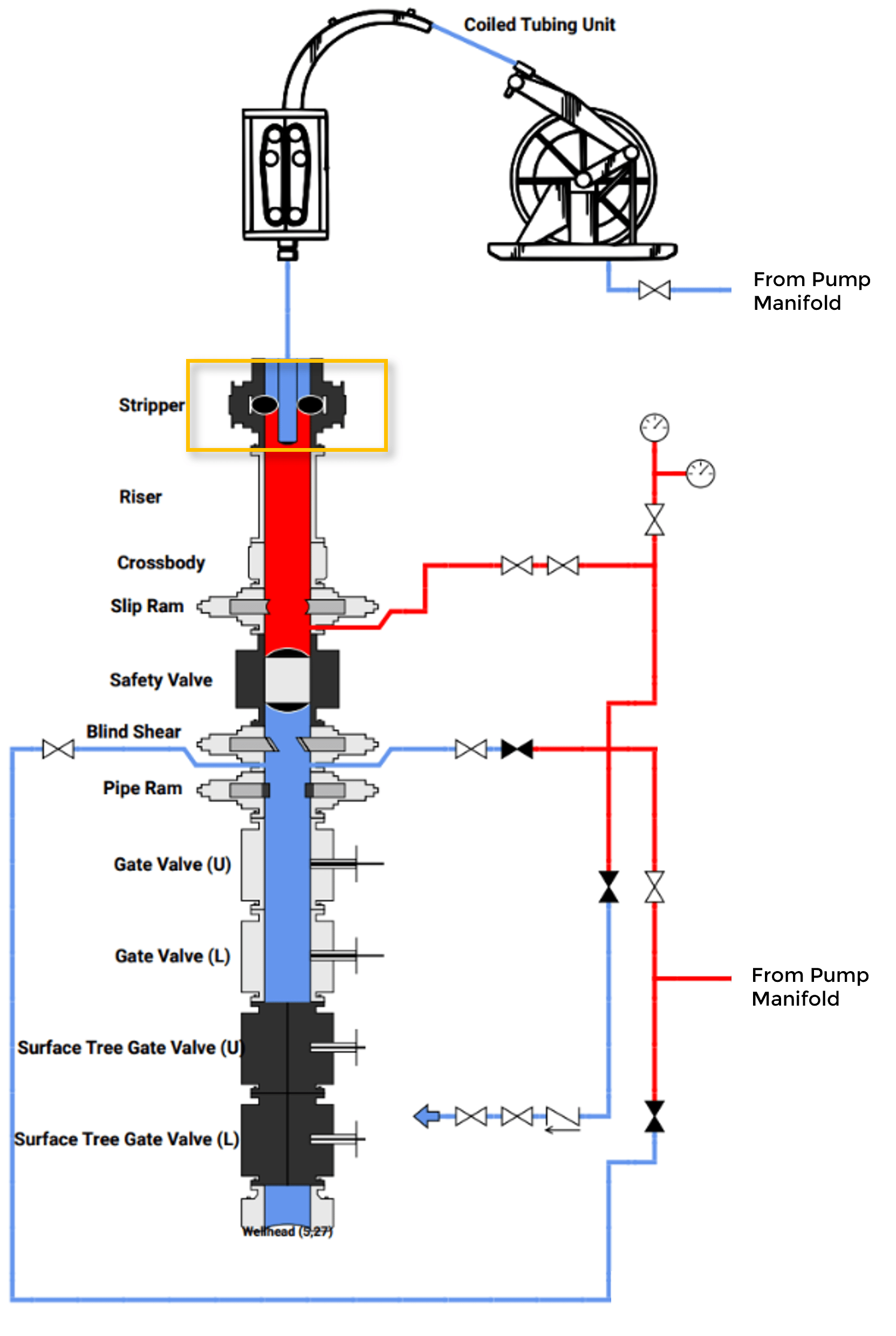
Well Control Stack Configurations
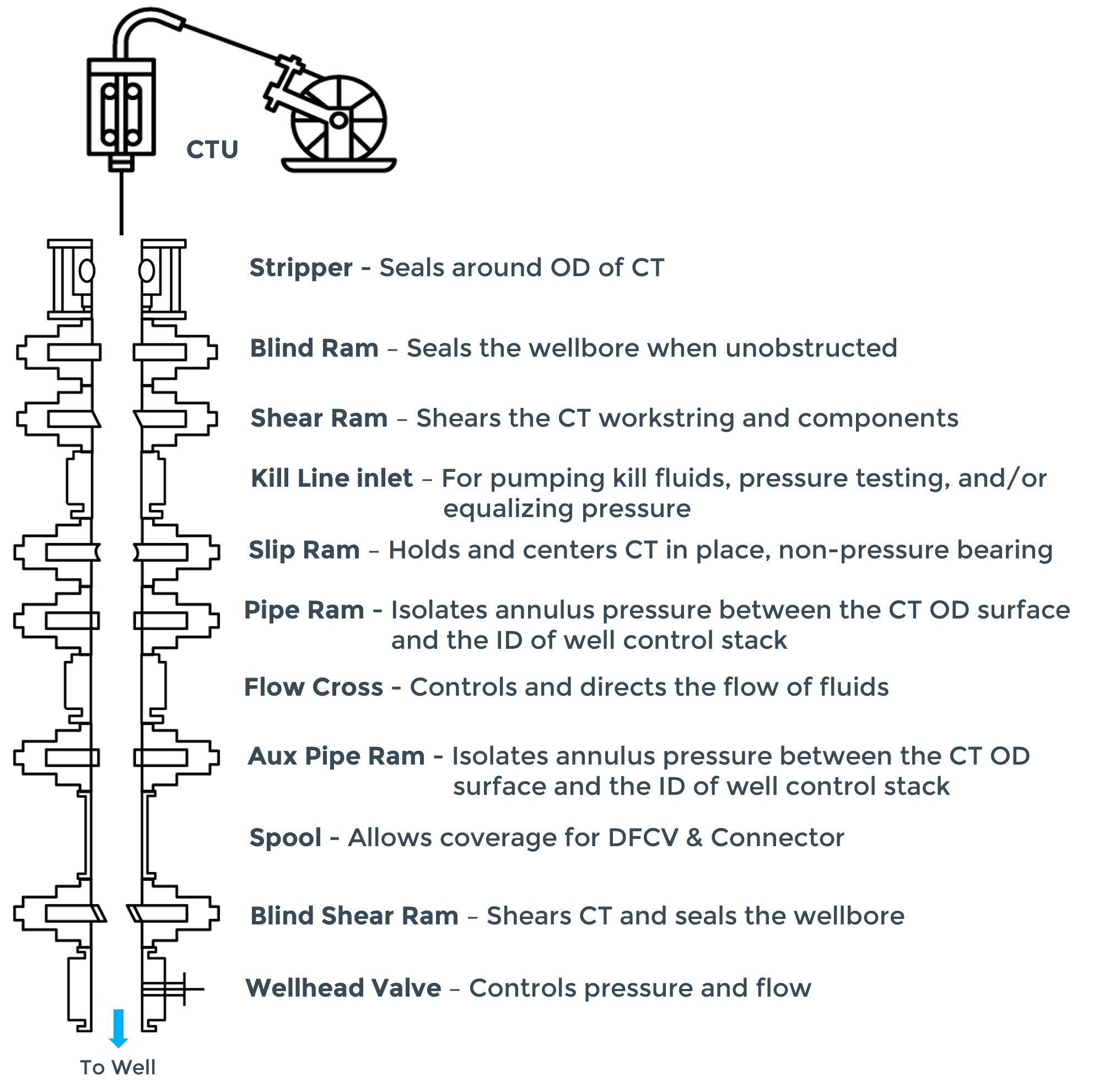
This section outlines the recommended order of components in the well control stack from the top down:
1. Stripper Well Control Component
2. Blind Ram Component
3. Shear Ram Component
4. Kill Line Inlet
5. Slip Ram Component
6. Pipe Ram Component
7. Dedicated SBR Component
Pressure Testing
All well control equipment must undergo pressure testing.
Testing Sequence
Low-pressure Test: Conducted between 250-350 psig, stabilized for at least five minutes without visible leakage.
High-pressure Test: Conducted at a pressure that is the higher of MAOP/MASP plus 500 psig, stabilized for at least 10 minutes without pressure dropping below the test value.
Frequency
Ram/Valve pressure tests: Required upon initial installation and after any event that compromises the pressure seals. Tests are required at least every seven days, but exceptions are allowed for ongoing operations preventing testing.
System pressure tests: Conducted upon initial installation and after any event that compromises the system. Tests are required at least every seven days, but exceptions are allowed for ongoing operations preventing testing.
Connection pressure tests: Performed if not included in the ram/valve tests or after any disconnection of a pressure seal.
CTU Well Control Stacks
The well control stack plays a critical role in flow control and well control in CTUs by sealing off the wellbore to contain unexpected flow and high pressures during drilling, production, and intervention operations. A typical well control stack used for CT operations is shown below. Actual stack configurations may vary based on the operator and the conditions encountered during coiled tubing operations.
Coiled Tubing Pressure Testing
As stated in the API RP 16ST, all well control equipment components should be pressure tested every seven days. The pressure test sequence for each component consists of a low-pressure test, followed by a high-pressure test. A component passes the LP test (from 250 psi to 350 psi) if the pressure stabilizes with no visible leakage for at least five minutes. The component then passes the HP test (MASP plus 500 psig) if the pressure stabilizes with no visual leakage for a minimum of 10 minutes and does not decrease below the intended test pressure. It can take several pressure test attempts to test all of the well control components. The figure below shows the stripper being pressure tested.
It’s common to pressure test multiple tools during a single well control stack test to improve testing efficiency. This is done by testing one tool, disconnecting the assembly, installing a second tool and then reconnecting the assembly. Typically, the test plan will need to include steps after this process that verify the connection point. Similarly, tools that are meant to stop pressure from coming up the coil (dual flapper check valves, wash heads, etc.) will usually need to be verified during the pressure test.
Optimizing Oilfield Performance with Coiled Tubing
CTUs play a critical role in oilfield operations, providing a range of applications from drilling to interventions. Coiled tubing’s flexibility and efficiency make it a valuable tool for optimizing well performance and maintaining well integrity. For details on IPT’s well integrity solutions, contact us.
IPT is committed to providing best-in-class customer service and support. If you need help choosing a solution that’s right for you, or if you need a hand from a pro in our 24/7 Real-Time Operations Center, we’re ready to serve you.