Formation Integrity Test (FIT): What You Need to Know for Ensuring Well Integrity
July 19, 2024
Understanding Formation Integrity Tests
The formation integrity test (FIT) is one of three types of formation strength tests, and it is used to evaluate the strength and integrity of a newly drilled section of well formation. After setting a section of casing and drilling out the casing shoe, several feet of new formation is drilled and the formation is gradually pressurized to a pre-determined pressure and then held during a subsequent shut-in stage. The FIT data is analyzed to verify the bonding strength of the cement around the casing shoe and to determine the maximum mud weight that can be used to drill the next well section. This test is essential to ensure that the formation can withstand the pressures it will encounter during drilling and production operations and to avoid loss of well control.
Importance of Oil and Gas Formation Integrity
The integrity of a wellbore changes with every drilled foot of depth, and mud weight is the sole pressure mechanism keeping the borehole stable. Formation Integrity Testing is vital for maintaining well integrity as it helps to prevent well control issues, such as blowouts and other hazardous events. In addition to verifying the maximum mud weight needed to drill the next well section, a FIT is used to compute the minimum mud weight required to prevent hole collapse and to evaluate the quality of the cement bond around the casing shoe. By verifying the formation’s ability to hold pressure, avoiding hole collapse, and assuring cement integrity, operators can substantially improve the safety and efficiency of drilling operations.
Preparing for the Formation Integrity Test
Follow Formation Integrity Test Safety Protocols
Essential safety measures during FIT include:
Verify the integrity of all pressure control equipment: blowout preventer (BOP), pressure gauges and transducers, bleed and shut-in valves.
Ensure proper communication among the drilling team
Prepare emergency response procedures in case of unexpected pressure surges or equipment failures.
Perform a Casing Integrity Test
After the casing or liner is cemented and before drilling out the cement at the shoe, a casing integrity test (CIT) is typically run to ensure the integrity of the casing or liner. During the CIT, drilling fluid is pumped into the casing or liner. The shut-in valve is closed when the target pressure is reached (below the maximum allowable pressure). If the pressure analysis passes specific criteria, the CIT is successful.
Casing Integrity Test
Establish Formation Integrity Test Guidelines
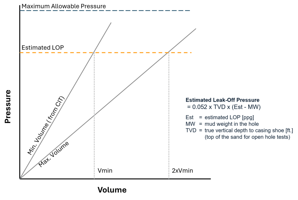
FIT guidelines are established to ensure that a valid test is conducted. The following guidelines below are used for reference during the test and subsequent FIT analysis.
Maximum Allowable Pressure – An upper constraint based on the limit of the equipment or lost circulation experience.
Estimated LOP – A prediction of the leak-off pressure; for a FIT, pressurization is terminated prior to reaching this pressure.
Minimum Volume – A lower constraint on the volume needed to be pumped during pressurization, based upon the volume pumped from the prior casing integrity test.
Maximum Volume – An estimated upper constraint on the volume needed to be pumped during pressurization (typically twice the volume required by the CIT); pressurization curves which fail to exceed this line are typically indicative of high formation permeability, which necessitate a repeated test with a higher pump rate.
Determination of Estimated LOP
Types of Formation Strength Tests
The standard FIT, the Leak-Off Test, and Extended Leak-Off Test are commonly known as formation strength tests. The different uses and procedures for these tests are described below.
Standard Formation Integrity Test
A standard formation integrity test involves gradually increasing the bottom hole pressure to a predetermined level to check the formation’s ability to withstand the pressure without leaking off drilling mud. Following a successful casing integrity test, FITs are generally performed using the following steps:
Drill out the cement and casing shoe 10-15ft (3-5m) of new formation – Pull downhole assembly back into casing to prevent sticking during FIT.
Clean and condition the wellbore – Connect the cement unit to the drill pipe and/or annulus to and circulate through an open choke line so that surface line is filled with drilling mud (no air in the system) before closing the choke line.
Close the BOP to isolate the wellbore – Close the annular or pipe rams around the drill pipe.
Gradually increase the pressure inside the wellbore – Slowly pump drilling mud down the kill/choke line with constant pump stroke.
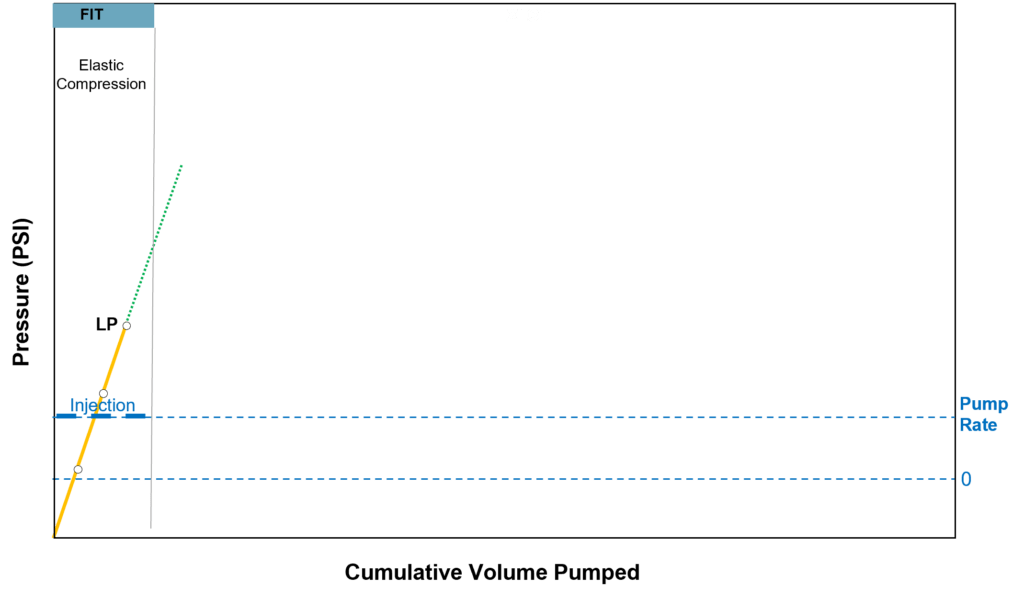
Record and analyze the pressure data – Plot the mud volume pumped and the surface pressure observed. Typically, the observed pressurization response is linear.
Stop the test before exceeding the estimated LOP – Stop the pump when the limit pressure (LP) is reached.
Determine the formation’s integrity – Analyze the FIT results.
Limit Pressure Reached for FIT
Leak-Off Test
A Leak-Off Test (LOT) is performed to determine the exact pressure at which the formation begins to fracture. It is often conducted at various depths during the drilling process to assess the formation’s pressure containment capacity. The key difference between the LOT and standard FIT is that the LOT involves a controlled increase in pressure until a small amount of fluid leaks into the formation, indicating the fracture point. This information is valuable for more accurately estimating formation stresses, which can be used to optimize the number of casing strings required.
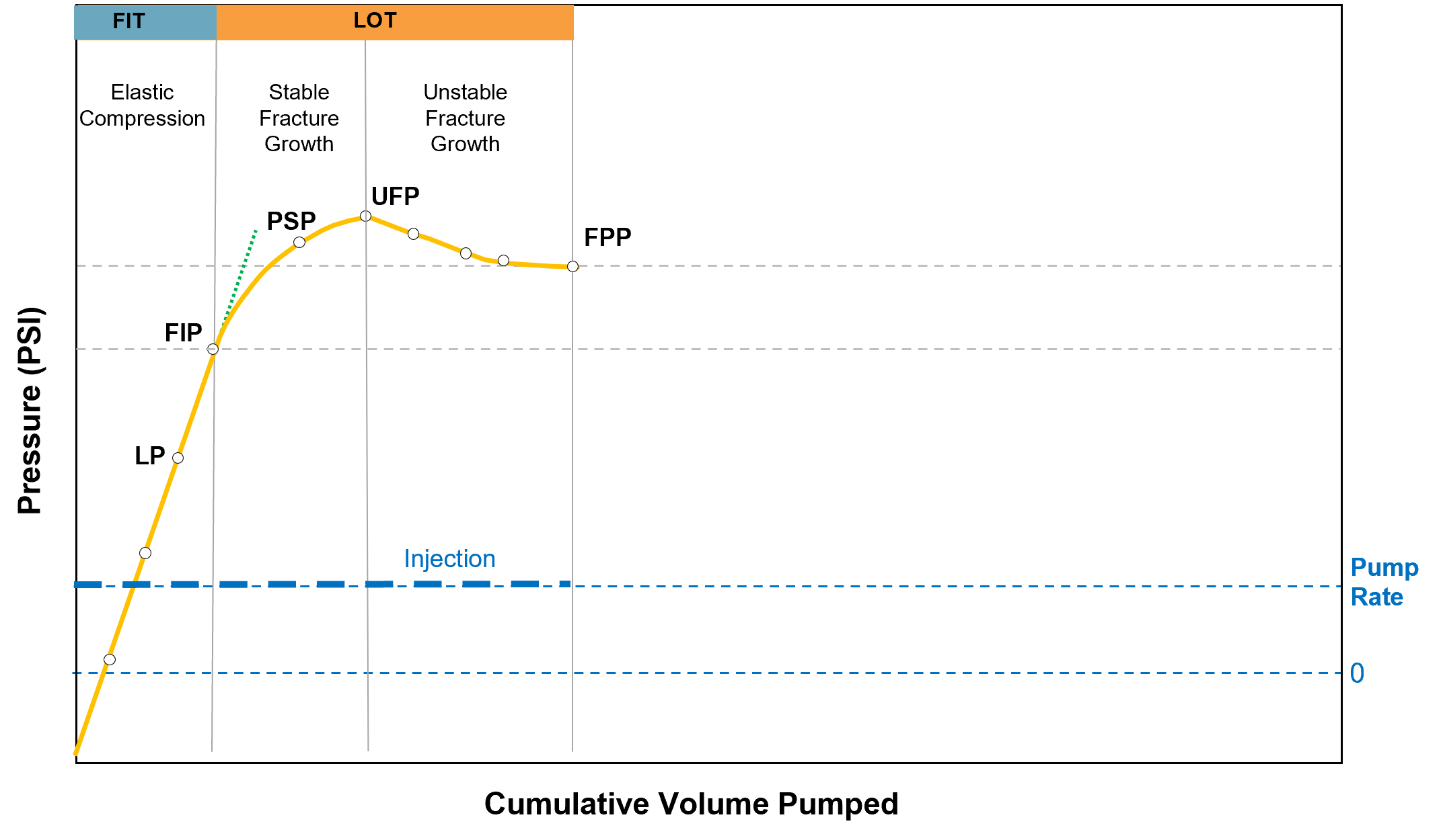
For a typical LOT, pressurization is continued past the LP until the wellbore pressure induces a stable fracture in the formation (fracture Initiation pressure). When the crack opens, fluid is lost to the formation across the permeable faces of the fracture. These fluid losses lead to smaller increases in pressure as additional fluid is pumped, which is indicated by the change in slope of the plot at a point called the fracture initiation pressure (FIP). The rising pump pressure at the surface up to the pump stop pressure (PSP) indicates stable fracture growth, as fluid is lost along the length of the fracture. After PSP, the fracture becomes unstable at a point called the unstable fracture pressure (UFP) because the fracture is extended away from the wellbore. When the pressure begins to asymptotically level off at the fracture propagation pressure (FPP), the test is concluded. Drilling operations then typically resume if the tests results permit the use of a suitable mud weight and if no cement channels are detected.
Typical LOT Plot
Extended LOT
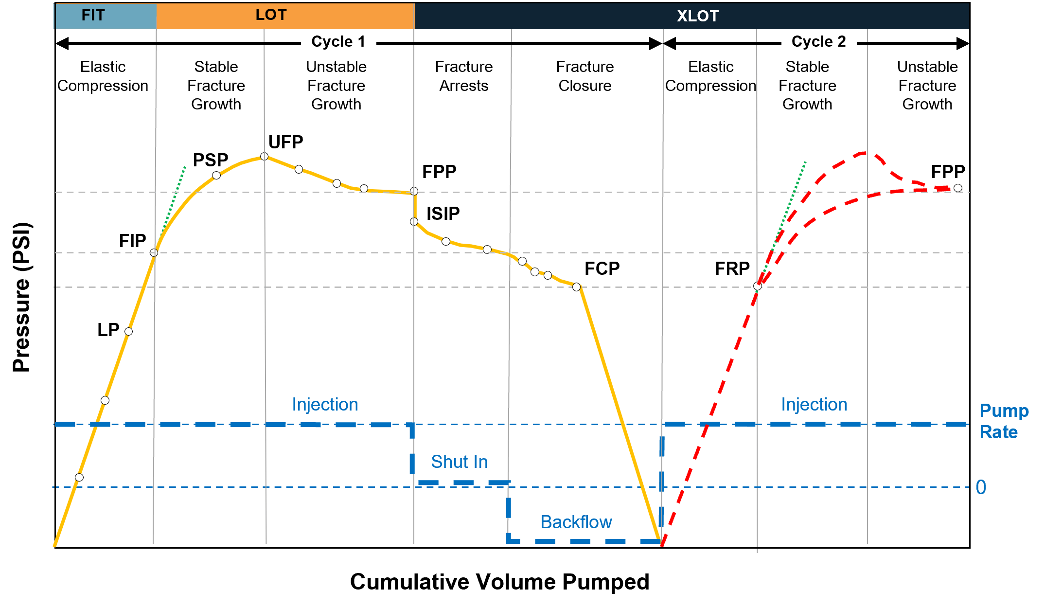
The XLOT is a series of LOTs that may be run to obtain horizontal stress data for predicting wellbore stability. The XLOT is a longer and more comprehensive test in which the mud continues to be pumped after the FIP is reached to determine the fracture closure pressure. Chronologically, the XLOT process consists of the following stages:
Fracture propagation – The fracture propagation pressure (FPP) is the point at which the fracture starts to propagate inside the formation.
Shut in – The instantaneous shut-in pressure (ISIP) is the pressure when the pump is shut off. A rapid drop in pressure may be seen due to fluid loss through the open fracture and loss of pump friction pressure.
Fracture closure – The fracture closure pressure (FCP) is the pressure at which the fracture starts to close. FCP usually equates to the minimum horizontal stress in the formation.
Fracture reopening – The fracture reopening pressure (FRP) is the pressure needed to reopen the fracture, which can only be observed in XLOT testing.
This process can be repeated multiple times to open and propagate the fracture to gather more data. The figure below shows an XLOT with a repeating cycle.
Typical XLOT Plot
Interpreting Formation Integrity Test Results
The results of a FIT are typically analyzed by visually interpreting pressure vs. time and pressure vs. volume plots or comparing them with theoretical models of formation behavior under stress. Key indicators of well integrity from FIT results include:
A gradual increase in pressure to the target pressure, showing the formation’s capacity to hold pressure.
Consistent pressure readings without drops, indicating no leaks or fractures.
To accurately analyze LOTs and XLOTs, multiple factors should be considered, such as formation permeability, fluid compressibility, stresses around the wellbore, and mud type.
Formation Permeability – Formation permeability affects fluid migration and pressure dissipation. During LOT/XLOT, low permeability formations show less fluid loss, while high permeability formations exhibit greater fluid loss, impacting the interpretation of pressure data and fracture initiation pressures.
Fluid Compressibility – The compressibility of drilling fluids influences the pressure response during the tests. Highly compressible fluids can lead to larger pressure drops, affecting the accuracy of formation strength measurements.
Wellbore Stresses – The stress regime around the wellbore is critical. LOT/XLOT measures the pressure at which the formation fractures. Understanding the in-situ stresses helps in determining the fracture gradient and ensures the applied pressures do not cause wellbore instability or collapse.
Mud Type – The type of drilling mud used affects the wellbore stability and the interpretation of LOT/XLOT results. Different mud weights and compositions alter the wellbore pressure profile and can influence the sealing efficiency and the formation’s fracture pressure.
Formation Strength Interpretation Challenges
The following factors can distort FIT, LOT, and XLOT results and lead to interpretation difficulties.
Non-linear Pressurization Response
Although the LOP is defined as the point where the trend of the pressure increase deviates from linearity, the pressure-volume trend prior to initiating a fracture can sometimes be non-linear. Factors such as air in the system or seepage caused by permeability in the formation can produce a non-linear pressurization response.
Incorrect Identification of the Leak-Off Pressure
Incorrect identification of FIP, also known as the leak-off pressure (LOP), can lead to a variety of problems and/or unnecessary expenses for a well. For example, if a lower than expected LOP is interpreted as a cement channel, the operator may conduct a squeeze job in an attempt to increase the LOP. However, if the low LOP is caused by a lower-than-expected fracture gradient, the operator will have wasted time and money on the squeeze job. Conversely, if a lower than expected LOP is interpreted as a low fracture gradient, when it is really caused by a cement channel, the operator may use an incorrect low value as an upper limit for mud weights. This could lead to prematurely setting the next string of casing or to choosing a dangerously low mud weight, which may not be able to control the well. Finally, if a LOP is misinterpreted to be higher than the actual LOP, an operator may use an excessive mud weight, which could lead to lost circulation problems.
Drilling Fluid Properties
The effect of drilling fluid properties can induce inaccuracies in the interpretation of surface-collected data, resulting in a higher pressure than the correct value.
Higher pump rates result in higher values for FIP and FPP. Since these pressures are recorded from gauges at the surface, higher pump rates result in higher pump friction which causes higher observed FIP and FPP values. These higher pressures are not an indication of formation strength. Therefore, it is suggested that LOTs be performed at the lowest possible pump rate.
High-Pressure, High-Temperature Wells
Deepwater HPHT wells have a lot of uncertainty regarding the integrity of the wellbore. These wells often experience significant deviations from the planned conditions. They can encounter very high levels of overpressure, intense heat, and formation pressures that are close to the point where formations can fracture.
Formation Integrity Test Best Practices
To minimize measurement distortions and improve the accuracy of FITs, LOTs and XLOTs, several best practices should be followed:
Accurate Mud Weight Control – Ensure the mud weight is accurately controlled and matched to the formation’s stress profile. This helps in maintaining wellbore stability and provides reliable pressure data during the tests.
Thorough Wellbore Cleaning – Thoroughly clean the wellbore to remove any debris or drilling cuttings that might obstruct pressure readings. This ensures that the pressure measurements are reflective of the formation’s response.
Proper Tool Calibration – Regularly calibrate pressure measurement tools and equipment to reduce the risk of erroneous data due to faulty equipment.
Use Less-Compressible Fluids – The type of mud will influence the trend of the LOT and XLOT especially during propagation stage. Water based mud (WBM) tends to be less compressible compared to oil based mud (OBM) or synthetic based mud (SBM).
Consistent Testing Procedures – Follow standardized procedures for LOT/XLOT to ensure consistency and reliability in the results. This includes adhering to recommended pressure increase rates and stabilization times.
Advanced Data Interpretation and Analysis – Use advanced data interpretation methods and software to analyze the pressure data. This helps to more accurately determine the formation integrity values.
Advances in Formation Integrity Testing
Recent advancements in FIT technology include the development of more accurate and reliable pressure measurement devices, real-time data monitoring systems, and improved software tools for pre-test planning, test execution and analysis.
More Accurate and Reliable Measuring Devices
Recent advances in measurement devices for LOTs and XLOTs have improved their accuracy and reliability significantly. These advancements include:
Digital Pressure Sensors – Digital pressure sensors offer higher resolution and accuracy compared to conventional analog sensors. Digital pressure sensors can detect subtle pressure changes, leading to more reliable test results.
Automated Data Recording – Advanced data logging systems automatically record pressure data throughout the test, reducing human error and providing continuous, high-resolution data for analysis.
Real-Time Data Monitoring Systems
Conventional formation integrity tests (FITs) for wells require closing the BOP and using the rig’s mud pumps, which can cause non-productive time (NPT). Alternatively, dynamic FITs can be performed using managed pressure drilling (MPD) without closing the BOP or incurring NPT. MPD methods use a closed-loop fluid system to accurately measure fluid flow in and out of the wellbore. These dynamic FITs can be conducted more frequently to verify that the wellbore can withstand the pressures associated with drilling fluids and well construction.
Improved Formation Integrity Test Software Tools
More software tools are available to aid in conducting FIT, including advanced data analysis programs that simulate well conditions to optimize test parameters and improve accuracy. Some software tools offer live monitoring and analysis for LOT and FIT for real time integrity assessment. More advanced software tools can be used for comprehensive well integrity and formation strength analysis.
Discover IPT’s Integrity Testing Solutions
Formation strength tests are critical processes in the oil and gas industry for ensuring well integrity and safety. Using advanced technology and adhering to the best practices will enhance the accuracy and reliability of these tests, contributing to safer and more efficient drilling operations. Contact us for information about IPT Global’s well integrity management solutions.
IPT is committed to providing best-in-class customer service and support. If you need help choosing a solution that’s right for you, or if you need a hand from a pro in our 24/7 Real-Time Operations Center, we’re ready to serve you.