Understanding Well Barrier Envelopes: Key Concepts and Importance
May 10, 2024
A widely accepted definition of well integrity is “the application of technical, operational, and organizational solutions to reduce risk of uncontrolled release of formation fluids throughout the lifecycle of a well”. Technical solutions refers to the physical well barriers that contain pressure and hydrocarbons. The failure of a well barrier compromises well integrity, resulting in loss of production and harm to personnel, environment, assets, and the operator’s reputation. Operational and organizational solutions include the planning, design, guidelines, and procedures that help achieve and maintain well integrity.
Two-Barrier Philosophy using Well Barrier Envelopes
A well barrier is often referred to as an envelope consisting of one or more well barrier elements (WBEs). Examples of WBEs include drilling fluid, BOPs, the wellhead, casing, cement, packers, and other well components. The failure of a single WBE can cause the well barrier envelope to fail. For wells that are capable of sustained flow to the wellhead, the O&G industry uses two barrier envelopes—primary and secondary—for a high level of reliability.
The primary barrier envelope consists of WBEs that are, or might be, in direct contact with well pressure to prevent unintentional flow of reservoir fluid to surface or another zone. The secondary barrier envelope consists of barrier elements that are, or might be, exposed to contact with well pressure should any primary barrier element fail.
Think of the primary barrier envelope as being inside the secondary barrier envelope. If an element that is part of the primary barrier envelope fails, the elements in the secondary envelope must prevent the release of reservoir fluid to the surface or to another zone.
Well Barrier Envelops Change Over Well Lifecycle Phases
The primary and secondary barrier envelopes change as wells progress through lifecycle phases, as shown in the table below. For example, the primary barrier envelope during drilling operations is the overbalance hydrostatic pressure from the drilling fluid, but during production the primary barrier envelope includes the casing, cement, production tubing, packers, and downhole safety valves. This is why it’s important for operators to have clear and accurate well barrier diagrams to help all stakeholders visualize changes to well barriers and assess risk over the life of a well.
Primary and Secondary Barrier Envelopes per Well Lifecycle Phase
Challenges and Potential Hazards to Well Barrier Integrity
With every well, there are challenges to assessing risks to well integrity. Well conditions change and there are multiple ways that well barriers can fail.
Challenges to Well Barrier Integrity
Wells are initially designed and constructed based on certain criteria. However, a well’s operating conditions or utilization may change during its lifecycle, adversely affecting the integrity of critical WBEs. For example, during the life of a well:
The changing wellbore environment may cause asphaltenes and hydrates to form.
The produced fluid may form scale in the production tubing.
WBEs may experience corrosion in high-pressure, high-temperature environments.
The well may be recompleted to zone with higher temperature and pressure than the original design.
Well stimulation (i.e., frac) can expose the well to a different pressure regime than the original design.
The well may be converted from production to injection, exposing it to higher pressure than the original design.
Produced fluid may contain particulates that erode production tubulars and other WBEs.
Any one or a combination of the above events can diminish the integrity of individual WBEs. Therefore, an effective well integrity management program is needed to validate the integrity of the WBEs to operating conditions that may be different from the original assumptions when the well was drilled.
Potential Hazards
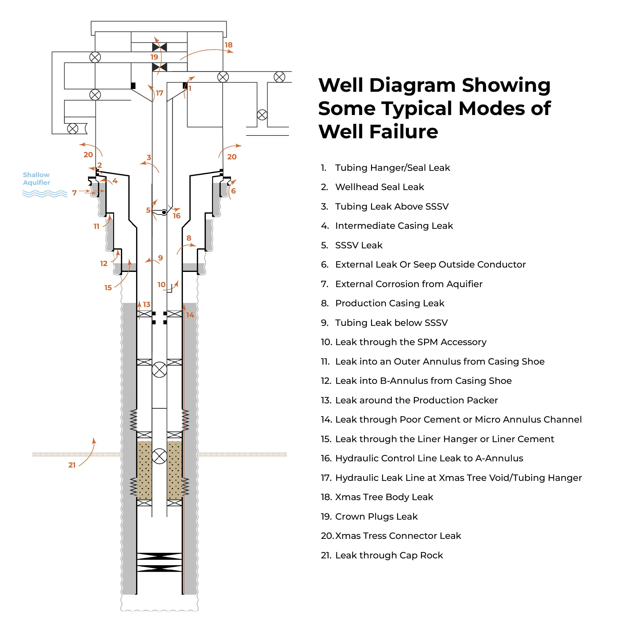
Well barrier elements can experience leak paths due to mechanical stresses, temperature changes, and exposure to corrosive substances. The figure below shows some of the potential leak paths in WBEs.
Strategies for Mitigating Risks to Well Barrier Integrity
Here are some strategies for mitigating risks to well barrier integrity:
Take all necessary steps during drilling operations to prevent explosions, blowouts, pollution, or other damage.
Assess and monitor chemical, mechanical, and physical factors: These factors include cement property evaluation, casing corrosion, acid gas concentrations, and harsh locations and downhole conditions.
Test and verify well barriers and their elements: This should be done upon installation and at intervals during the well’s lifetime.
Design and Implementation of Well Integrity Management Systems
Regulatory Compliance and Standards
International industry associations and standardization organizations have issued the following standards, guidelines and recommended practices related to well integrity.
API STD 53, 4th Edition, Jan 2012
“Blowout Prevention Equipment System for Drilling” is a standard that provides requirements for the installation and testing of blowout prevention equipment (BOP) systems on land and marine drilling rigs.
API RP 96, 1st Edition, Jan 2013
“Deepwater Well Design and Construction” is a recommended practice (RP) that aims to improve safety and reduce the chance of losing well control or damaging the environment. It includes considerations for barrier and load cases. This RP is based on the complexity of deepwater operations, which requires a thorough understanding of well design criteria and the equipment associated with them.
NORSOK D-010 Revs 4, Jun 2013
“Guidelines for Well Integrity in Drilling Well Operations” is the Norwegian O&G industry standard that defines the minimum functional and performance requirements for well barriers throughout a well’s life cycle. The standard focuses on how to conduct operations and what equipment should be used and is concerned with drilling, completion, and abandonment activities.
ISO/DIS 16530-1, 2017
“Well Integrity – Life cycle governance” offers guidance to well operators on managing well integrity throughout the well’s life cycle. It is intended for use in the petroleum and natural gas industries worldwide and applies to all wells regardless of their age, location, or type. This part of ISO 16530 addresses the minimum compliance requirements for well operators to claim conformity with this part of ISO 16530. The document addresses each stage of the well life cycle, as defined by six phases: the basis of design, design, construction, operation, intervention, and abandonment.
Planning and Design Tools – Well Schematics and Well Barrier Diagrams
Well schematics and well barrier diagrams are two distinct methods of illustrating WBEs and their role in integrity management. Each method has its specific applications, contributing to a comprehensive understanding of well integrity management strategies.
Well Schematics
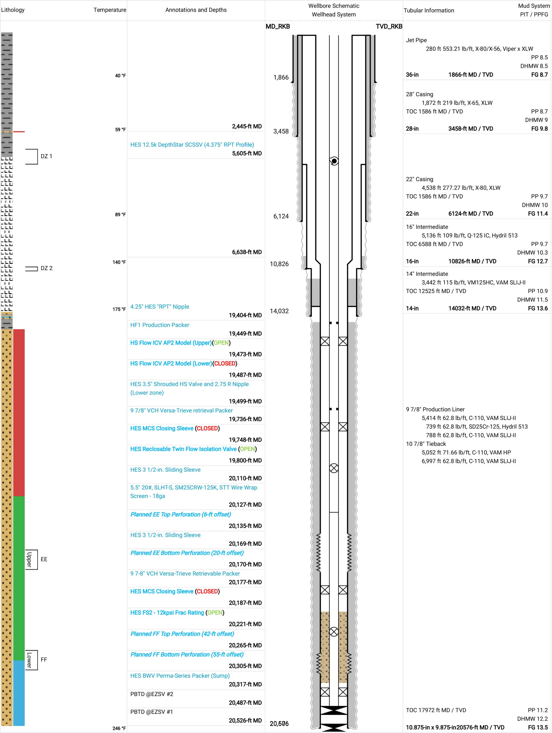
A well schematic is an illustration that shows the arrangement of the main WBEs within the well system. The schematic typically includes well and location information, annotations that describe the lithology, depths of the casing and cement sections, descriptions of the major WBEs, mud weights, and formation temperatures.
Well schematic outputted from IPT’s WellSchematic wellbore diagramming tool
For years, engineers have used various applications to create well schematics including spreadsheets, word processors, CAD programs, and other planning tools. This has resulted in duplicate data entry with increased potential for errors, change management challenges, and communication and workflow issues during handovers between well phases. Digital well schematic software allows engineers to build well barrier plans in a centralized cloud-based repository that tracks the location and information about each WBE in every well.
Digital well schematics provide several benefits:
Visualizes what is in the well, including clear barrier schematics and tables containing information on each WBE.
Creates a single source for wellbore schematics, test plans, and barrier plans.
Saves time by eliminating duplicate data entry in multiple applications.
Improves accuracy by reducing the potential for human error.
Updates plans automatically so everyone has the latest version.
Simplifies communication and workflows among stakeholders from planning to abandonment.
For seamless well diagramming, reach out to IPT and discover our user-friendly tool! Contact us now to explore how our easy well diagramming tool can revolutionize your workflow.
Well Barrier Diagrams
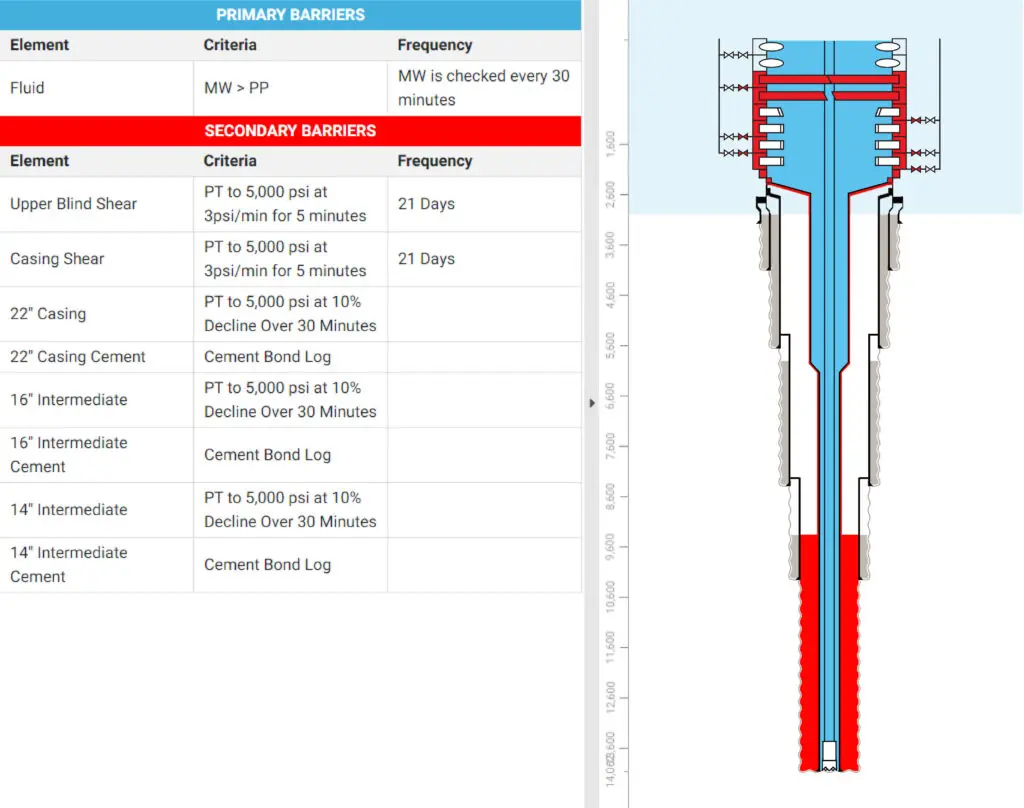
Well barrier diagrams display color-coded primary and secondary barrier envelopes and may illustrate all potential leak paths from the reservoir to the surrounding environment. These diagrams describe the status of barrier elements and are valuable for evaluating the consequences and likelihood of specific scenarios. Well barrier diagrams quantify the likelihood of consequences depicted in the diagram, making them useful for risk assessment and decision-making.
Digital well barrier diagrams provide some of the same benefits as well schematics, plus:
Visualizes primary and secondary well barriers and makes sure everyone sees the same diagram.
Reduces risk by providing a clear understanding on how to protect wells from planning to plug and abandonment.
Documents the well barrier status in a centralized location accessible by all authorized to see the information.
IPT’s well barrier management tool for building barrier diagrams and plans
Emerging Technologies to Assure Well Barrier Integrity
Well integrity software applications define the commitments, requirements, and responsibilities of an organization to ensure the integrity and safety of oil and gas wells throughout their lifecycle. The primary aim is to mitigate the risks associated with uncontrolled releases of formation fluids, which can lead to environmental harm, injuries, and financial losses. This is achieved by identifying potential integrity threats, implementing preventive measures, and regularly monitoring well conditions to prevent leaks or failures. IPT offers rigorous well integrity software and expert advisory services for advanced well integrity management at every stage of the well lifecycle. The software encompasses tools for constructing detailed wellbore schematics, which serve as the foundation for developing barrier schematics and plans essential for test planning and generating comprehensive test plan reports with complete documentation of surface and subsea WBEs to be tested. IPT’s integrity tests leverage proprietary algorithms that significantly reduce pressurized time for testing WBEs and remove validation subjectivity, saving rig time and reducing risk. Additionally, IPT’s well integrity management solutions allow collaboration and handover among teams, while tracking all changes and maintaining versions over the complete lifecycle of wells. IPT’s expert advisors are available to support the process wherever required, whether onsite or remotely. With decades of experience, they excel in generating and optimizing integrity test plans, offering expert assistance before, during, and after testing operations, regardless of location worldwide.
Ready to Ensure Well Integrity? Contact Us Today!
Ready to enhance your well integrity management? Contact us today to learn more about our advanced software solutions and expert advisory services. Don’t wait—reach out today to ensure the safety and reliability of your oil and gas wells.
IPT is committed to providing best-in-class customer service and support. If you need help choosing a solution that’s right for you, or if you need a hand from a pro in our 24/7 Real-Time Operations Center, we’re ready to serve you.