
Situation
During a routine offshore BOP stump test, standard validation indicated acceptable results with no clear signs of failure. Pressure readings were stable, no alarms were triggered, and the system met conventional pass criteria.
However, traditional BOP pressure testing is designed to detect leaks, not subtle emerging issues. In this case, the system would likely have been cleared for deployment with an undetected integrity risk.
Solution
SureTec® PressureTesting TestEngine utilizing advanced leak detection analysis. Rather than relying solely on pass/fail thresholds, this approach evaluates:
This deeper analysis identified a subtle but consistent degradation in pressure trend; behavior inconsistent with a fully sealed system and easily overlooked using conventional methods.
Results
Following the analysis:
Operational Impact
By shifting the focus from “Did the test pass?” to “Does the data behave like a truly sealed system?”, the TestEngine analysis uncovered a developing leak that would have otherwise gone unnoticed. Early leak detection enabled proactive intervention, delivering measurable value:
Lessons Learned
This case reinforces a critical insight into traditional well control operations: passing a BOP pressure test does not guarantee system integrity. Subtle leaks can evade standard validation methods, progress under real operating conditions, and lead to high-impact offshore failures if left undetected.
By moving beyond pass/fail testing and understanding how pressure behaves over time, operators can detect what others miss, protecting both operations and the bottom line.
Ensuring well integrity throughout a well’s lifecycle is essential for maintaining safe and efficient operations in the oil and gas industry. Effective annular casing pressure (ACP) management is key to preventing problems with well barrier elements (WBEs) such as casing leaks, sustained casing pressure (SCP), and subsea safety valve (SSV) malfunctions. Implementing a structured ACP monitoring and reporting system ensures transparency during operational handovers and provides an auditable record for forensic analysis if required. Without effective integrity management, operators risk unnecessary well shut-ins and costly interventions.
The illustration below shows the standard designations for the “A”, “B”, and “C” annuli in a subsea well. The “A” annulus is the void between the production tubing and the smallest casing string while the “B” and “C” annuli are the voids between the successive outer casing strings.
The sealed annuli contain trapped fluids that later become heated by the high flow rate of formation fluids during production. The hotter fluids expand, causing an increase in the annulus pressure on the well. Eliminating any pressure fluctuations due to thermal effects, a pressure change in the “A” annulus is an indication of a leak. The pressure measured at the wellhead in the “A” annulus, or in the other annuli that terminate at the wellhead, is called the annular casing pressure (ACP).
Annular casing pressure (ACP) is a primary indicator to detect leaks within the barrier envelope. Deviations in pressure within the “A” annulus may indicate leaks in one of the barrier elements, excluding the Downhole Safety Valve (DHSV). Troubleshooting involves adjusting pressure in the adjacent “B” annulus and the production tubing to identify the failing barrier element. The rate of pressure change can help assess well integrity risk levels.
A production packer anchors the tubing string and isolates the “A” annulus from both the formation and the tubing’s interior. Leaks in these seals or any connections can lead to SCP within the “A” annulus. For subsea wells, only the pressure in the “A” annulus can be monitored and bled down, while surface and land wells allow monitoring and bleeding at the wellhead.
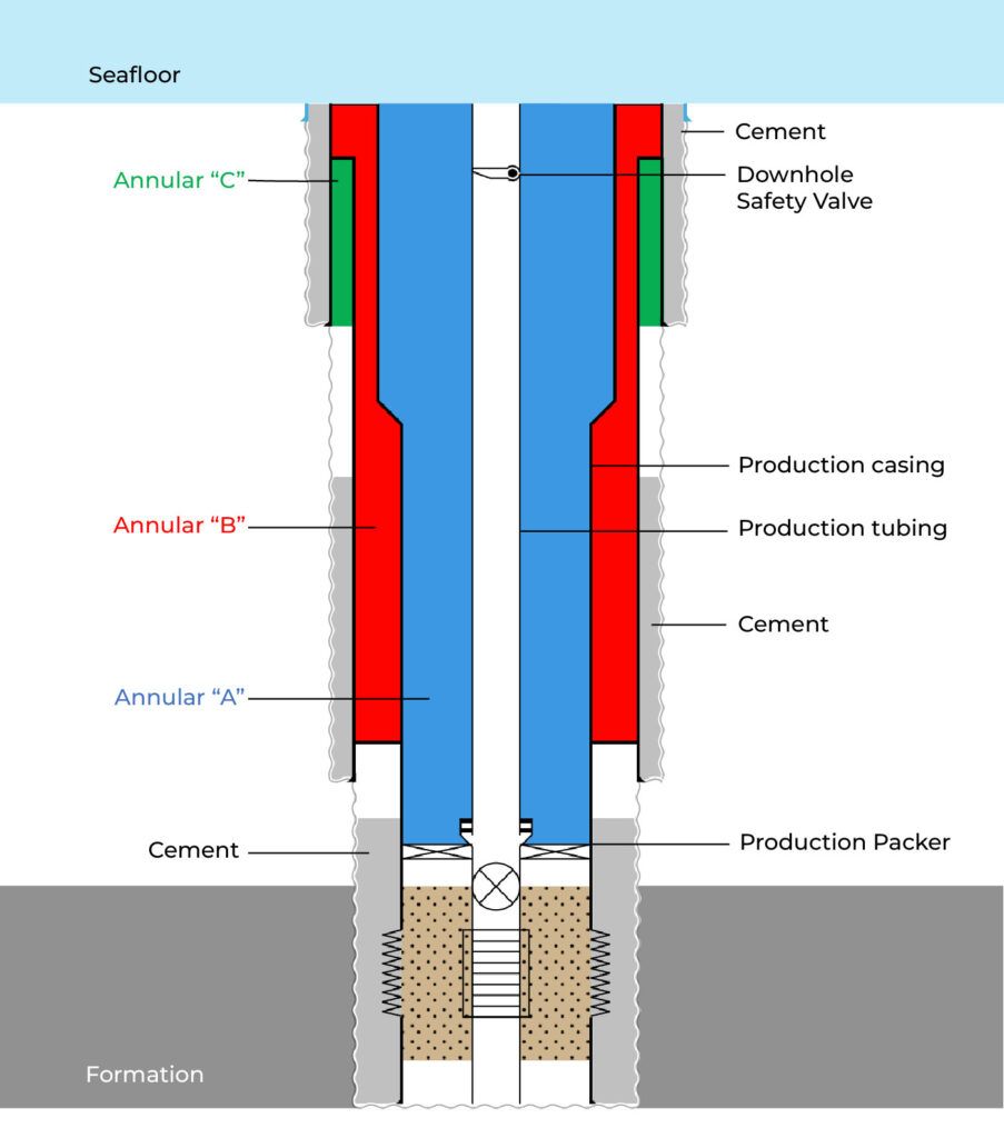
API Recommended Practice (RP) 90-1 identifies three sources of annular casing pressure:
Of the three pressure sources, SCP is the only one that will rebuild once bled off. SCP may result from communication with a pressurized formation or from a barrier that inadvertently creates a flow path. The following potential communication paths can affect the “A” annulus and the “B” and “C” annuli.
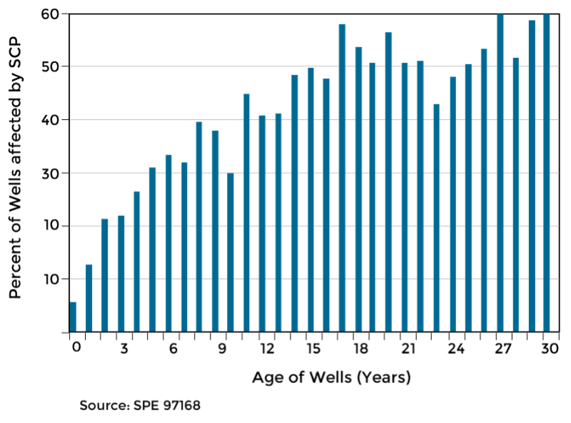
The occurrence of SCP tends to increase throughout a well’s lifecycle, from drilling to abandonment. Continuous monitoring of ACP is therefore considered best practice.
API RP 90-1 Section 9 outlines recommended procedures for monitoring annular casing pressure (ACP) in offshore wells. It highlights the importance of equipping all accessible annuli with the ability to monitor pressure, perform bleed-offs, and inject fluids when necessary. Initial pressure testing should be conducted to establish baseline values and identify any existing ACP resulting from operational conditions.
Regular monitoring is essential, with operators responsible for setting a minimum frequency to ensure pressure remains within diagnostic limits. The section distinguishes between operator-imposed and thermally induced pressures and emphasizes the need for close observation following any operational changes.
When sustained casing pressure (SCP) is detected outside of acceptable thresholds, the frequency of monitoring should be increased. For inaccessible annuli, a formal risk assessment is required to determine the feasibility of restoring monitoring capabilities and to assess the implications of any pressure sources.
Overall, this section offers a comprehensive framework to support safe and effective ACP management and ensure long-term well integrity.
Annular casing pressure management is a critical component of well integrity management. By understanding the causes of ACP fluctuations, implementing best practices, and leveraging digital solutions, operators can proactively prevent integrity failures, minimize costly interventions, and enhance operational safety. Standardized reporting, automated data collection, and routine diagnostics ensure regulatory compliance and long-term sustainability. Investing in a structured ACP management strategy ultimately protects assets, personnel, and the environment. For more information on how our digital solutions can enhance your well integrity management, contact IPT Global today.
IPT and Horizon56 have partnered to deliver an integration designed to enhance efficiency and assurance during operations. With the integration of IPT’s SureTec and Horizon56’s RigFlow, operators can now visualize live pressure tests in real-time alongside other critical operations, all within a single, streamlined platform.
The integration of IPT’s application within Horizon56 RigFlow transforms the way operators view and manage their operations. With Remote View part of RigFlow, users can monitor integrity assurance tests while executing DOPs—all from a single screen. Gone are the days of switching between platforms to access critical operational data.
This integration provides a holistic view of your operations, allowing operators to watch live pressure tests as they take place, check plan steps, and add comments in real time. By combining these capabilities into a single interface, Horizon56 and IPT make it easier than ever to ensure efficiency, accuracy, and smooth communication throughout the operation.
Watch live pressure tests as they occur within the broader scope of your operations. Stay updated in real time without switching between multiple systems or platforms.
Add comments and check off plan steps as they are completed, all within the same interface. The ability to communicate directly on each step enhances clarity and reduces the risk of miscommunication.
Operators and rig crews can visualize every step of the process in real time, ensuring that all operations are being carried out in the correct order.
By consolidating rig operations across different software platforms into one interface, this integration significantly reduces inefficiencies, helping to improve workflow and reduce errors.
One of the biggest challenges in operations is managing different processes tracked across various platforms. This can lead to gaps in communication, errors, and inefficiencies. The integration of IPT’s SureTec with Horizon56’s RigFlow addresses this issue by providing a seamless, real-time view of all critical operations.
With Horizon56 and IPT, you can be assured that your team has access to all necessary information for efficient well operations—whether it’s pressure test results, operational steps, or direct communication with your crew.
If you’re ready to take your operations to the next level with real-time insights and unified platform, contact us today to learn more about the integration between IPT SureTec and Horizon56 RigFlow.
Ensuring well integrity is critical in offshore operations to ensure safety and efficiency in oil and gas production. Pressure tests are vital for confirming that well components can withstand the pressures encountered during operations. Just as important are the reports that document these tests, serving as a historical record and helping track the well’s performance over time. Implementing a digital pressure testing solution with integrated reporting capabilities and adhering to best practices for report generation, ensures the data is accurate, clear, and compliant with industry standards.
A major challenge in pressure test reporting is ensuring data accuracy, as errors in data collection or transcription can lead to incorrect assessments of well integrity. Digital pressure testing software, such as IPT SureTec, addresses this issue by automatically converting test data into reports, ensuring the information is accurate, complete, and consistent.
Regular audits further ensure that these reports meet regulatory standards, helping companies avoid fines and penalties.
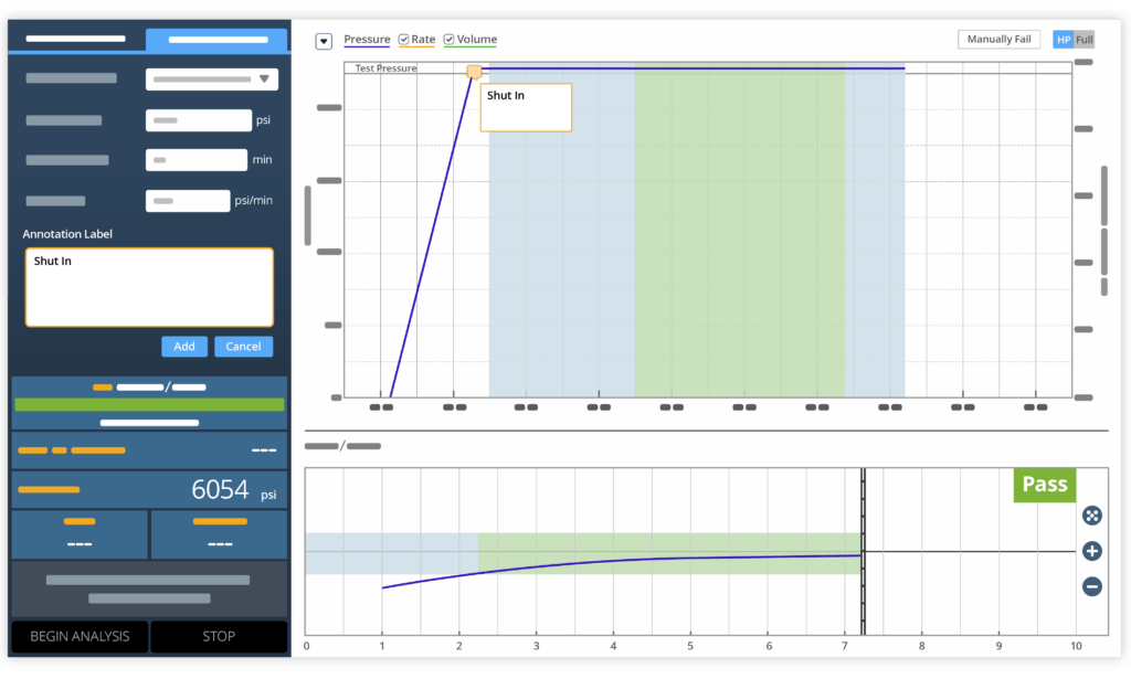
Pressure tests may sometimes provide results that are unclear or on the edge of acceptable limits when readings fluctuate or are close to preset thresholds. To address this, detailed documentation of test conditions and consultation with experts are essential to determine if further testing is needed.
IPT SureTec’s digital testing software enables detailed notetaking during testing, ensuring clear documentation of uncertainties, which supports informed decision-making regarding well integrity.
A major challenge is ensuring consistent documentation across various test types and wells. Variations in report formats or terminology can cause confusion and make it hard to compare results. Standardized templates and report structures resolve this issue by ensuring that the same format is used for all tests.
IPT provides standardized test reports, making it easier to interpret and compare results across multiple tests.
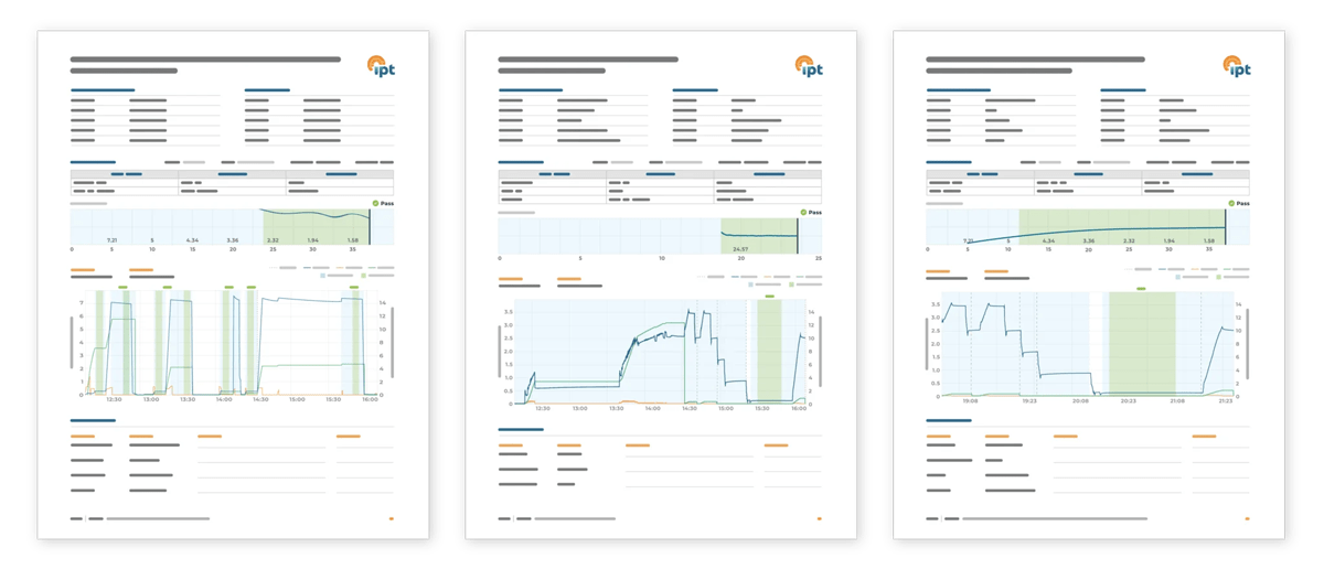
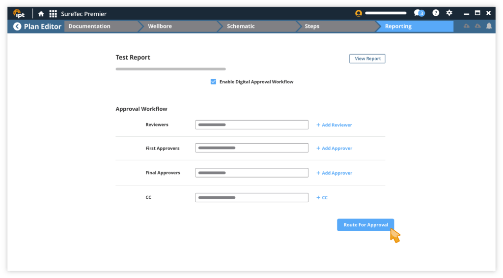
Test plan reports and test results must be submitted to key stakeholders for review, approval, and signatures. Traditional manual paper-based processes for approving reports often result in delays, lost documents, and version control issues. Ensuring traceability during report handover and approval is crucial for regulatory compliance, while accountability and transparency also enhance business processes.
Digital approval and handover processes reduce the risk of delays, lost paperwork, and version control issues, ensuring reports are quickly approved and stakeholders have access to the most up-to-date version. IPT’s software enables digital distribution of test reports for instant approval, with an audit log tracking all approval activities.
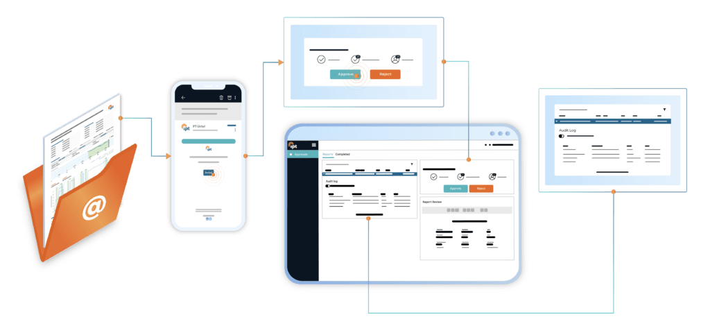
Utilizing IPT’s SureTec and SureView applications offers significant advantages in generating and managing well integrity test reports. SureTec is a desktop testing application, facilitating the creation of test plans and executing tests. It generates standardized reports, detailing each test step, including pressure graphs, schematics, and comprehensive documentation of tested components. With built-in compliance features, SureTec ensures that all reports meet industry standards and regulatory requirements. Test plan and test reports can be routed instantly from the platform upon completion of setting up a test plan or running a test.
Testing data, reports, and analytics are stored in IPT’s cloud-based SureView application, which also supports watching tests remotely in real-time. SureView includes an audit log for tracking all approval activities and allows digital distribution of reports for handover and approval. It also facilitates long-term data storage and easy retrieval, ensuring seamless access to historical test data.
Effective pressure test reporting is crucial for maintaining well integrity and operational safety. Leverage IPT’s solutions to streamline the process, enhance data accuracy, ensure documentation consistency, and simplify handover and approval workflows. For more information on how our digital solutions can enhance your well integrity management, contact us today.
Coiled tubing (CT) is a long, flexible, metal or composite pipe with no joints that is used in the oil and gas industry for a variety of purposes:
Coiled tubing has several advantages, including increased efficiency, cost effectiveness, and safer operations. Some of its disadvantages include limited depth and borehole size, high maintenance costs, and reduced accuracy. This article describes the operation and applications for coiled tubing units (CTUs), and it specifically covers the well control stack and industry recommended practices for pressure testing coiled tubing.
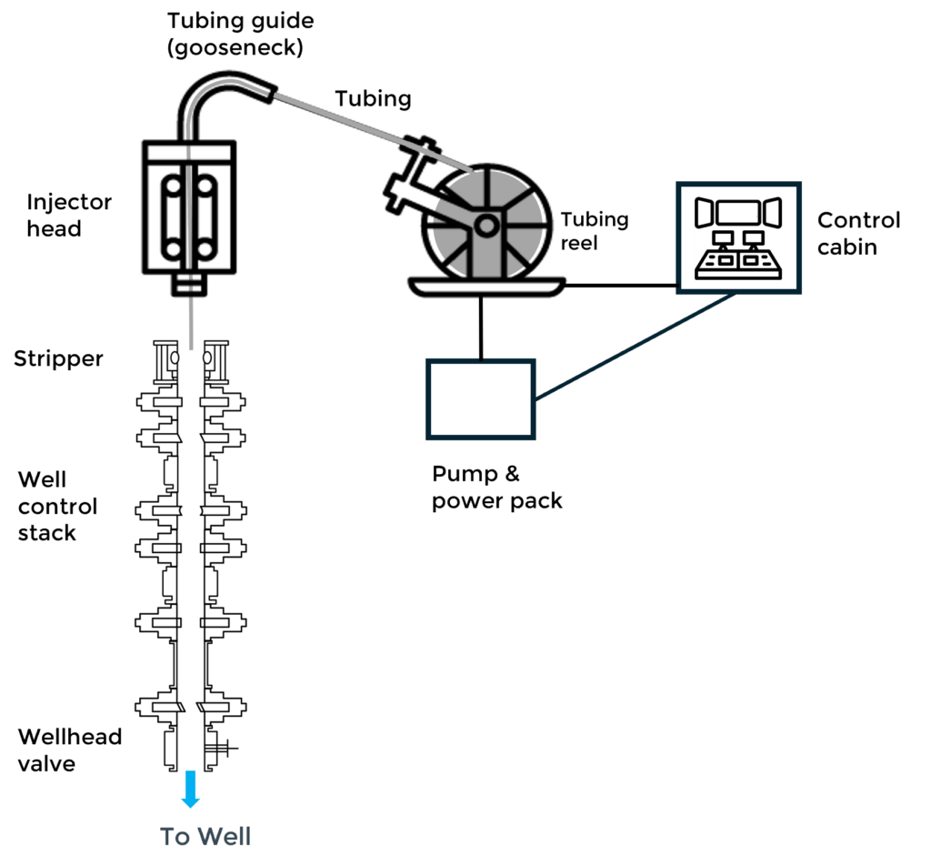
Coiled tubing units (CTUs) include the following components:
Coiled tubing can be used for drilling operations without the use of drill pipe and a rotary table, which speeds up the process. A bottom hole assembly (BHA) with a drill bit is connected to the coil tubing and inserted in the well. The injector head pushes the tubing into the well and the BHA uses a motor or rotary steerable system that rotates the drill bit. The BHA is essential for directional drilling and wellbore navigation.
A downhole mud motor may also be used in coiled tubing drilling operations to convert the hydraulic energy of the drilling fluid into mechanical energy to rotate the drill bit independently of the coiled tubing string.
Coiled tubing is a beneficial tool for circulation in well interventions due to its continuous length’s ability to navigate complex wellbores. Most often, the operation will involve pumping nitrogen or various fluids to free the well of light debris (sand) and removing water or condensates built up during production.
Coiled tubing allows the deployment of logging tools into the wellbore to collect data about the formation and well conditions, such as formation pressure, fluid composition, temperature and formation properties. This is especially useful in highly deviated or horizontal wells where traditional wireline logging might be challenging.
Subsea lubricators dictate the length of perforating guns that can be run when using conventional drill pipe. Coiled tubing simplifies perforating operations by allowing the use of long bottom hole assemblies (BHA) while maintaining dual well control barriers. This enhances safety and operational efficiency.
Coiled tubing can be connected to pumping units and inserted in a well to pump fluids for various treatments, including well stimulation, hydraulic fracturing, acidizing and cementing. The ability to pump the fluid without interruption while continuously inserting the coiled tubing allows a steady and controlled flow rate.
Coiled tubing can be used for various production enhancement techniques, such as gas lift or artificial lift systems, contributing significantly to improved efficiency and reduced downtime. In gas lift installations, CT enables more efficient and precise placement of gas lift valves along the tubing string, especially in deep or deviated wells. In artificial lift systems, CT significantly reduces installation time for electric submersible pump systems in shallow gas wells to address liquid loading issues.
CT is valued for its flexibility, efficiency, and ability to perform a wide range of tasks without the need for a rig, making it an essential tool in offshore well interventions.
The CT operator in the control cabin manages the entire process of deploying and retrieving the tubing during CT operations. Coiled tubing is spooled off the reel and passes through a tubing counter that measures the length of the tubing being deployed and retrieved. The tubing is then guided through a gooseneck and directed downward to the hydraulically driven injector head, which the CT operator uses to control the movement and depth of the CT string. The tubing becomes straight before it enters the well control surface stack.
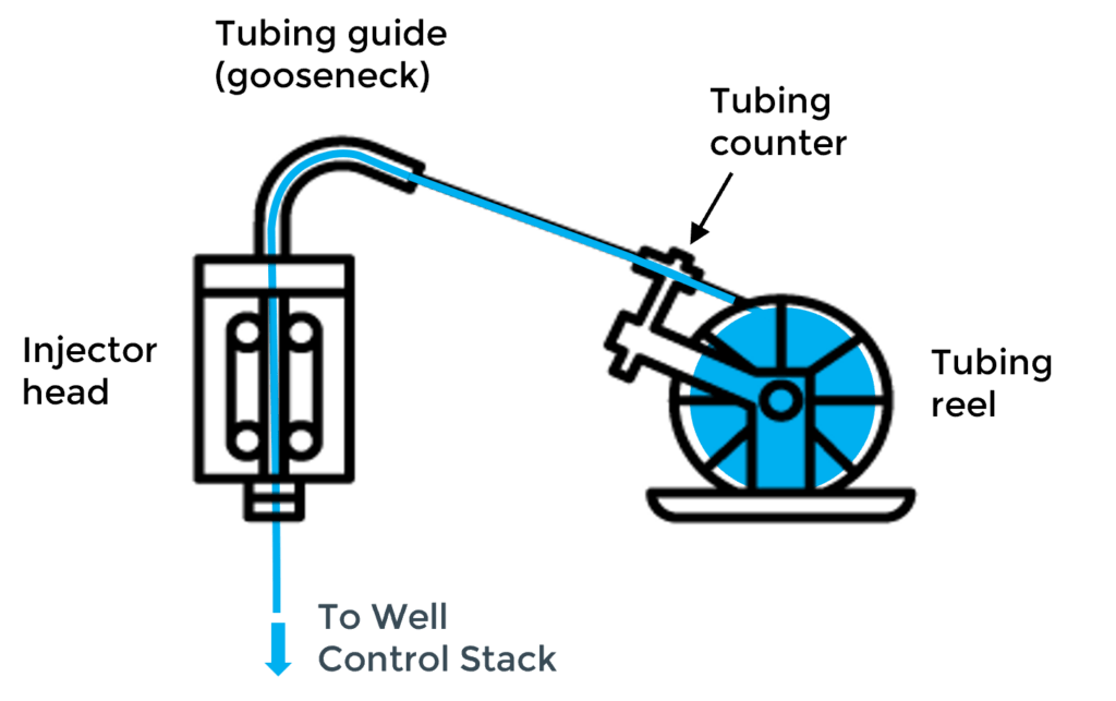
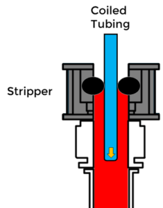
Beneath the injector head, the stripper assembly on top of the well control stack provides a dynamic seal around the tubing string, which is crucial for running the CT in and out of live wells.
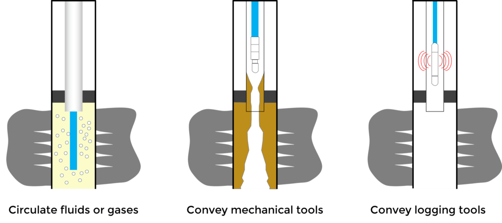
During intervention operations, CT can be used to circulate acid, nitrogen or cement. Devices may also be conveyed down the tubing for purposes such as sealing, cleaning, or initiating other downhole operations. For example, balls may be pumped down the tubing to isolate sections of the well, or darts may be used to trigger tools and other chemical treatments. The CTU uses hydraulic pressure to push these devices down the tubing and through a dual-flapper check valve. The flow of hydraulic fluid is carefully controlled to ensure the devices travel to reach their target accurately. Coil tubing also allows logging tools to be deployed down the wellbore to collect data about the formation and well conditions. The CT Operator monitors the movement of devices in real time using sensors and telemetry systems.
At the end of the operation, the tubing is pulled out of the well and spooled back onto the reel. A high-pressure swivel joint on the reel hub allows fluid to be pumped while the reel rotates.
Coiled Tubing operations are governed by regulatory standards and recommended practices to ensure safety and efficiency. Key standards and recommended practices are 30 CFR Part 250 Subpart G and API RP 16ST, respectively. 30 CFR Part 250 Subpart G is a mandatory federal regulation for outer continental shelf operations, whereas API RP 16ST is a voluntary industry standard. The recommended practices in API RP 16ST offer detailed guidance to support and enhance compliance with the regulations set forth in 30 CFR part 250 sub part G.
API RP 16ST (Recommended Practice for Coiled Tubing Well Control Equipment Systems) is a crucial standard governing coiled tubing operations. The second edition, along with its Addendum 1 from February 2022, provides updated guidelines for well control equipment systems used in coiled tubing operations to ensure enhanced safety and operational efficiency. A summary of some of the key sections of the recommended practice are listed below.
A coiled tubing (CT) well control barrier is defined as a tested mechanical device, or a combination of devices, designed to prevent the uncontrolled release of wellbore fluids.
Key components include:
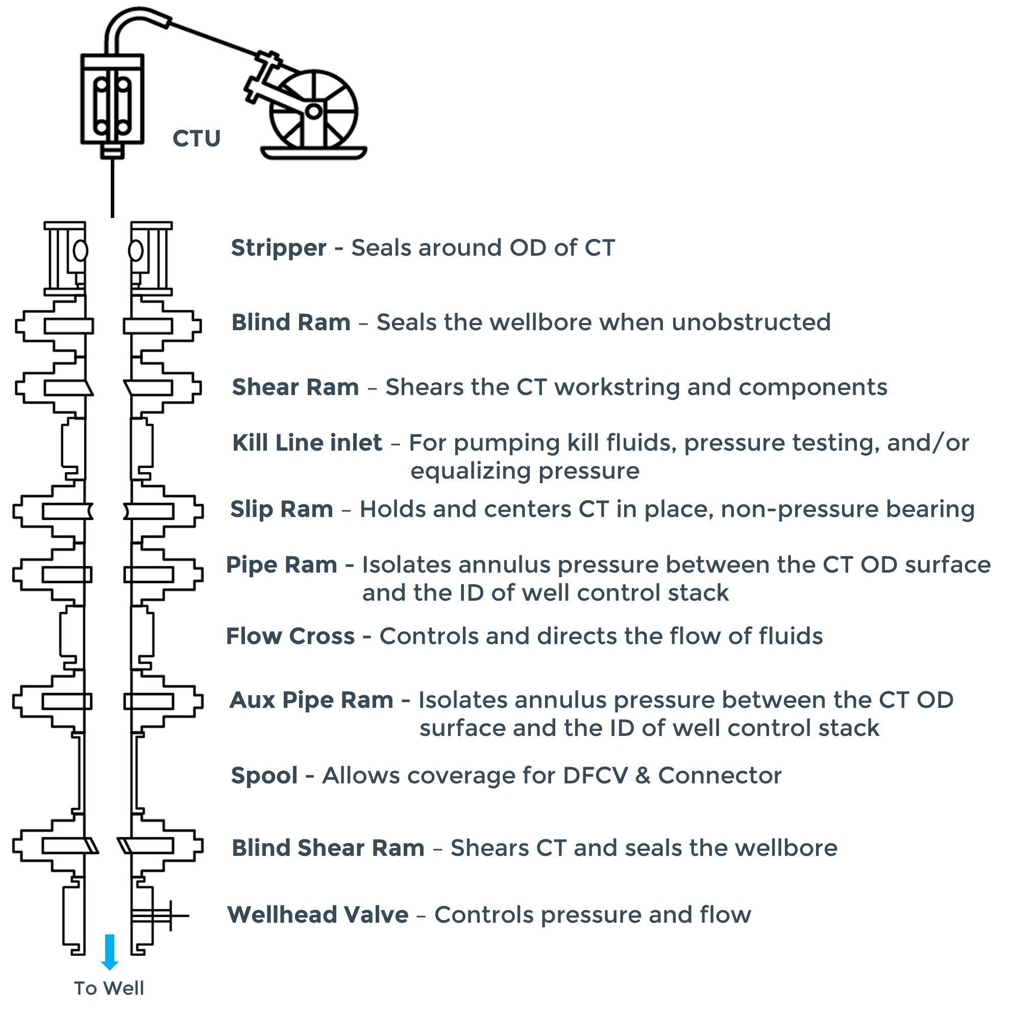
This section outlines the recommended order of components in the well control stack from the top down:
1. Stripper Well Control Component
2. Blind Ram Component
3. Shear Ram Component
4. Kill Line Inlet
5. Slip Ram Component
6. Pipe Ram Component
7. Dedicated SBR Component
All well control equipment must undergo pressure testing.
The well control stack plays a critical role in flow control and well control in CTUs by sealing off the wellbore to contain unexpected flow and high pressures during drilling, production, and intervention operations. A typical well control stack used for CT operations is shown below. Actual stack configurations may vary based on the operator and the conditions encountered during coiled tubing operations.
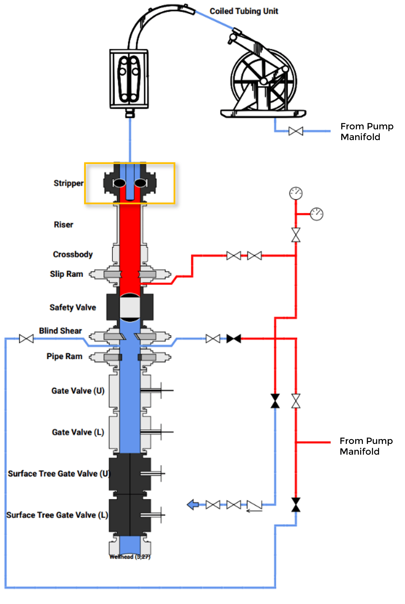
As stated in the API RP 16ST, all well control equipment components should be pressure tested every seven days. The pressure test sequence for each component consists of a low-pressure test, followed by a high-pressure test. A component passes the LP test (from 250 psi to 350 psi) if the pressure stabilizes with no visible leakage for at least five minutes. The component then passes the HP test (MASP plus 500 psig) if the pressure stabilizes with no visual leakage for a minimum of 10 minutes and does not decrease below the intended test pressure. It can take several pressure test attempts to test all of the well control components. The figure below shows the stripper being pressure tested.
It’s common to pressure test multiple tools during a single well control stack test to improve testing efficiency. This is done by testing one tool, disconnecting the assembly, installing a second tool and then reconnecting the assembly. Typically, the test plan will need to include steps after this process that verify the connection point. Similarly, tools that are meant to stop pressure from coming up the coil (dual flapper check valves, wash heads, etc.) will usually need to be verified during the pressure test.
CTUs play a critical role in oilfield operations, providing a range of applications from drilling to interventions. Coiled tubing’s flexibility and efficiency make it a valuable tool for optimizing well performance and maintaining well integrity. For details on IPT’s well integrity solutions, contact us.
Marine Well Containment Company and Helix Well Containment Group (MWCC and HWCG) are skilled in maintaining and developing capping stacks. IPT partners with these consortiums to validate the capping stack integrity prior to deployment to prevent oil leaks. IPT provides rapid, efficient, and transparent capping stack testing that reduces testing time and ensures reliable deployment. Pressure tests can be viewed from anywhere with IPT’s cloud-based application creating transparency for operators, contractors, and regulators alike.
A capping stack is a device used to control the flow of oil and gas from a well in the event of an emergency or unplanned release of hydrocarbons.
The capping stack can be placed on top of a wellhead. The capping stack contains a number of valves and control systems that can be operated remotely to shut off the flow of oil and gas.
In the event of a well blowout or other emergency, a capping stack can be deployed to contain the release of hydrocarbons and prevent further damage to the environment.
Since the Deepwater Horizon Incident in 2010, regulations have been put in place to require the availability of capping stacks as a response measure in case of a catastrophic incident.
Capping stacks have been developed with advancements in technology and increased awareness of the importance of well control and blowout prevention.
However, the use of capping stacks gained significant attention following the Deepwater Horizon oil spill in 2010. The spill was one of the worst environmental disasters in history, sending millions of barrels of oil into the Gulf of Mexico. The spill continued for 87 days before the well was finally capped.
In response to the Deepwater Horizon incident, the oil and gas industry, government agencies, and regulators placed increased emphasis on well control and blowout prevention. The first subsea capping stack was deployed in 2011, as a response to the Deepwater Horizon oil spill in the Gulf of Mexico. The capping stack was designed and built by a consortium of oil and gas companies, including ExxonMobil, Chevron, ConocoPhillips, Shell, and BP, along with service companies, mainly Trendsetter Engineering, through a working partnership with the US government.
The subsea capping stack was specifically designed to be deployed in deepwater environments, where traditional capping stacks were not effective. The device was capable of withstanding high pressures and temperatures and could be deployed using remotely operated vehicles (ROVs).
The subsea capping stack was tested and validated in a series of simulated blowout scenarios before being deployed to the site of the Deepwater Horizon incident. The device was successfully used to cap the well, bringing the oil spill under control after 87 days of uncontrolled release.
Since then, subsea capping stacks have become a required component of offshore drilling operations, with regulations mandating their availability in case of emergencies. The development and deployment of subsea capping stacks have improved the ability to respond to well blowouts and other emergencies, minimizing the impact on the environment and human life.
The US Bureau of Safety and Environmental Enforcement (BSEE) published new regulations in 2016 that require operators of offshore drilling operations in US waters to have access to well capping systems capable of controlling the flow of hydrocarbons in the event of a blowout. These regulations have led to increased development and deployment of capping stacks.
There are now over a dozen capping stacks spread geographically across areas ready to be deployed at a moment’s notice. The two Gulf of Mexico consortiums, Marine Well Containment Company and Helix Well Containment Group are comprised of highly skilled employees, engineers and contractors that maintain and develop capping stacks to be deployed at a moment’s notice.
In any emergency situation, rapid response is critical to minimizing the impact of an incident. Great emphasis is placed on preparedness and response planning, including the pre-positioning of equipment and the training of personnel in well control and emergency response procedures. Not all well containment scenarios are the same, and many factors could influence the necessary response. If a capping stack is needed, it must be tested prior to deploying subsea. This includes a pressure test to validate the integrity of the capping stack to prevent an oil leak. IPT provides well integrity assurance through the use of advanced algorithms to detect leaks. This is applied on capping stacks to determine the integrity of the capping stack prior to deployment. IPT provides clear and actionable results in real time that can be broadcasted on IPT’s cloud-based application to anyone in the world.
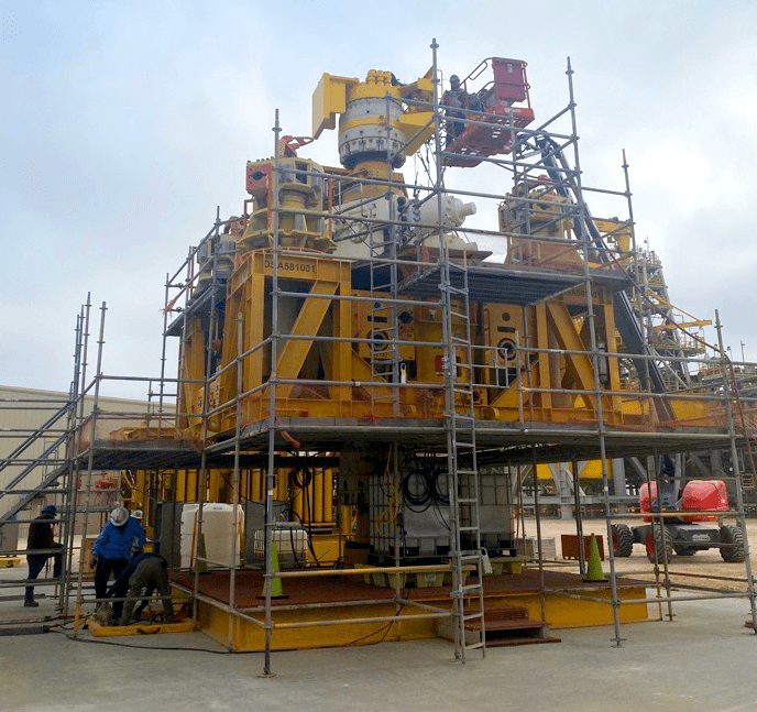
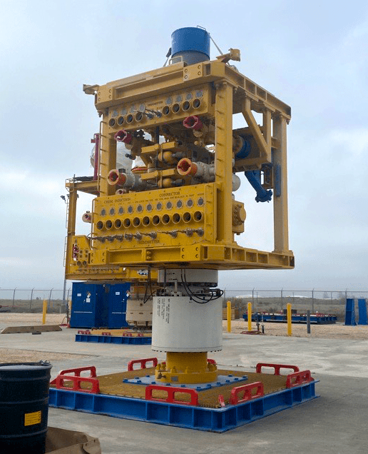
IPT provides pressure testing assurance with the use of Thermally Compensated Leak Detection (TCLD) analysis which compares the natural thermal pressure decay to determine if there is a leak. IPT’s TCLD provides more efficient pressure testing of capping stacks. Prior to March 2023, Trendsetter Engineering was relying on the traditional method of pressure testing, however IPT worked with Trendsetter to create a pressure test procedure with TCLD. As a result, IPT was able to reduce the amount of time on pressure by two hours. This time savings also aided maintenance operations where pressure testing went from taking two days to only one.
Because Capping Stacks are pressure tested prior to deployment, every minute counts in reducing the harm to the environment.
As an industry we strive for our commitment to protecting personnel and the environment, we hope to never need to use a capping stack to stop an oil spill but are prepared to deploy one at a moment’s notice and have made large strides in reducing the response time. IPT has assisted MWCC & HWCG in reducing the time required testing capping stacks and providing an industry leading integrity assurance.
Pressure test may be broadcasted through IPT’s cloud base application. Consortium members and regulators alike are able to witness the capping stack testing in real time, anywhere in the world. This creates transparency where operators, contractors and regulators can witness and collaborate during testing in real-time regardless of their location.
IPT collaborates with the consortium through the use of onshore maintenance testing and system integration testing prior to the deepwater deployment drill. IPT draws on extensive industry experience to advise on testing criteria for this unique type of well control equipment.
IPT is proud of working in the oil and gas industry to help demonstrate the confidence a capping stack can be reliably deployed, and integrity tested using IPT’s software. Contact us to learn more about our capping stack testing capabilities.
IPT Global’s services and technologies came together to deliver value to all stakeholders during a well intervention program in Angola, off the west coast of Southern Africa. The intervention services company (ISC) had an extensive program and its objective was to have its personnel perform the integrity tests with remote support from IPT, which includes our Field Advisors and Real-Time Operations Center (RTOC). The ISC’s goal was to demonstrate the ability to provide turnkey intervention services for various operators. IPT’s team worked with the ISC to create a custom operational support plan that consisted of in-house and on-site training, planning and test execution optimization, and remote support.
IPT provided pre-deployment training at its office for the ISC’s engineers and managers. The training focused on using existing test plans to run tests and publish reports. Several variations of the test plans were run using existing schematics. IPT provided setup guides for the digital acquisition (DAQ) unit and transducers, along with quick start guides to run various tests in SureTec. The participants were able to experience live data acquisition via the SureTec simulator, allowing them to become familiar with the SureTec interface during testing.
At the site, IPT’s Field Advisors trained intervention personnel so they could run SureTec with remote support from our RTOC. The training focused on using a testing matrix to guide testing efforts, leveraging the RTOC for remote support and publishing tests. IPT’s RTOC and engineers helped to manage the testing program with handover and record archival while transitioning between wells.
The operator planned 28 integrity tests, with specific criteria for each of the test types performed. IPT engineers created a test matrix for the ISC that included the operator’s criteria and a procedural reference for each test, making review and approval easier. The test matrix also helped ISC personnel to manage the testing program by making it easier to locate and run previously built test plans on the testing laptop. This allowed the company to focus on their operations and setting up the hardware rather than having to set up each test plan.
Completed tests and reports were uploaded to SureView for archival and traceability. SureView is a secure, web-based tool that also provides real-time status of pressure tests, test data organization and retrieval by well and date, advanced data analysis, and remote viewing of active tests.
The ISC received remote support from our RTOC, which is staffed by engineers and experienced advisors (RTOAs) who monitor all pressure tests 24/7 and provide global technical support. Remote support ranges from assisting with data connections, networking issues, and basic software issues to advanced support such as:
The intervention program required 28 integrity tests with various operator criteria to be performed over a relatively short period. The ISC successfully executed the intervention program and achieved its primary goal of providing turnkey service with technology and remote support from IPT. SureTec’s digital accuracy, objectivity, and flexibility assured the integrity of all tested components according to the operator’s criteria. Our engineers performed post-test reviews to ensure that all components were tested to the proper pressure as dictated by the operator. Our RTOAs verified that test reports were published properly to assure the traceability of all integrity tests for hand off to the production team and to provide an auditable trail of compliance for local regulatory bodies.
In addition, the integrity tests had to be performed safely and efficiently to avoid costly rig-time delays. Preparation began with effective training of the intervention crew by our experienced trainers. Our engineers assisted the operator and ISC by building accurate test plans and creating a test matrix that reduced the possibility of delays due to human error and increased the efficiency of hardware setup by the production and intervention crews. Most importantly, the ISC was able to deliver the intervention program safely to protect people, the environment, assets, and the reputations of all stakeholders.
To learn more on how our integrity solutions can you provide you the assurance necessary for well interventions, contact us!
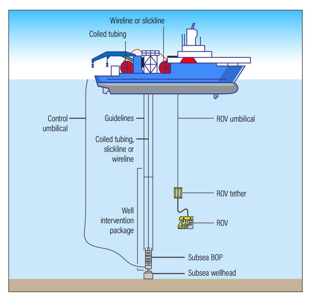
Well Interventions may be performed to add or restore production or to fix a well integrity issue. Expected production gains from deep and ultra-deep subsea wells must justify the cost of offshore intervention vessels and crews. Light well interventions are more common and cost-effective because they can be performed with minimal shut-in of the well. Light well interventions include, but are not limited to, acid stimulation; sand, scale, or hydrate removal; and gas lift remediation. In light well interventions, tools or sensors are lowered into a live well using slickline, wireline, or coiled tubing while pressure is contained at the surface. Service companies can perform light well intervention operations through subsea wellheads using riser or riserless methods while using a ROV to perform the operation and guide the landing of the well intervention equipment as shown in the stimulation example below.
Each intervention program has specific objectives, operational steps, and associated risks. To enhance the safety, reliability, and assurance of the program, IPT offers integrity testing and assurance for a wide range of systems and components.
Subsea well interventions involve many challenges and require comprehensive planning to mitigate risk. IPT’s SureTec application is a single solution that handles all facets of integrity test planning for intervention operations. Interventions require a large number of integrity tests with varying criteria to be performed over a relatively short period. SureTec improves efficiency and project management, and it reduces risks by allowing operators to use consistent and stringent criteria for validating integrity-critical WBEs.
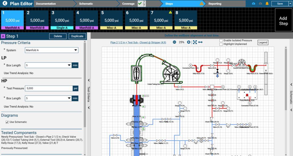
SureTec’s planning tools allow designers to build interactive schematics, wellbore diagrams, and test plan steps for stump, BOP, deck, coil tubing, positive and negative (inflow) test plans. SureTec’s Schematic Editor provides drag-and-drop components that accurately depict the operation of surface and subsea equipment. These schematics are integrated seamlessly into test plans that clearly identify test criteria and precisely simulate valve states and pressurized paths as shown in the following figure.
IPT’s support includes a Real-Time Operation Center (RTOC) staffed by engineers and experienced advisors (RTOAs). Our engineers assist operators and intervention service companies by building test plans in SureTec that accurately represent their testing program. An engineering team member can also create a test matrix that provides a snapshot of all tests and criteria as well as guidelines that help the production and intervention crews with hardware setup. Our RTOAs are responsible for reviewing intervention test plans to ensure all critical components are tested to the appropriate pressure.
IPT’s support includes a Real-Time Operation Center (RTOC) staffed by engineers and our Field Our Field Service Quality Advisors (FSQAs) or trained intervention service company personnel use SureTec to perform pre-deployment activity testing of the well intervention equipment, the manifold, and other surface iron to assure that the intervention tools and well control components work properly prior to their deployment on the vessel. SureTec provides component integrity assurance with high digital resolution and stringent test criteria. Digital resolution and sensor accuracy are vital because high measurement sensitivity is required to detect small pressure changes in control lines, and small-volume cavities and annular spaces.
Upon the vessel’s arrival at the well, our FSQAs or trained rig crew use SureTec to ensure the integrity of the system that will connect to the well as this system will protect people, equipment, and the environment during the latch up phase.
During installation on the seafloor, the tree cap is removed, and the well stimulation tool is connected (latched) to the subsea tree. After the well access tool is latched up (e.g., a stimulation tool), IPT performs a connector test to verify the integrity of the system.
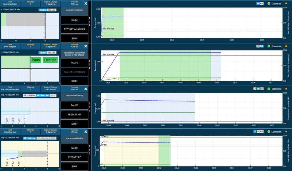
During intervention operations, integrity tests must be performed thoroughly and efficiently because any avoidable delay in critical path operations can increase risk and be costly for both the intervention service company and the operator. Efficient testing of critical components requires the ability to connect to various sources and run multiple tests simultaneously. SureTec receives data from multiple sources such as the IPT transducer, ROV transducer, ROV control system, and Workover Control System. Users can enter Multi-Test mode to execute up to four test plans simultaneously, each with a different pressure source and test criteria. Users can start, stop, and restart analysis for each test independently.
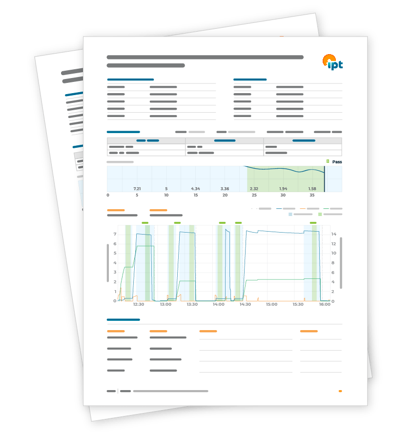
After the intervention is completed, the operator also needs traceability of all integrity tests to hand off to the production team and to have an auditable trail of compliance with local regulatory bodies. When each test is completed or stopped, SureTec generates a standardized, detailed report of each test step, including pressure graphs, schematics, and complete documentation of tested components. Our RTOAs review the test files to ensure all tests passed and all components were tested to proper pressures. They also verify the integrity of barriers before the intervention team departs.
The documented data and lessons learned from each intervention fosters an environment of continuous improvement and delivers the highest-level integrity assurance to operators, production operations, and intervention service companies.
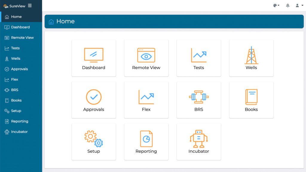
Operators’ intervention and production teams can use IPT’s SureView application for report archival and traceability over the entire lifecycle of the well. SureView is a secure, web-based tool that provides real-time status of pressure tests, test data organization and retrieval by well and date, advanced data analysis, and remote viewing of active tests. SureView’s interactive search features simplify retrieval of historical test data for review and analysis.
IPT’s comprehensive planning, test execution, and reporting tools combined with our team of experts contribute to better management and mitigation of potential risks leading to improved performance and greater assurance of well integrity during well interventions. Contact us to discuss your well interventions.
For over a century, the oil and gas industry has relied on outdated technology and individual experience to interpret pressure tests that are critical to verifying well integrity for the protection of personnel, the environment and equipment.
Digital pressure testing provides an objective interpretation using accurate and high-resolution data that is tamper-proof and auditable. Additionally digital data allows for cloud-based archival of the well history and KPI tracking to make performance visible to identify learning opportunities, and close process safety gaps while reducing opportunities for human error.
An important and visible change associated with digital data was the move 10+ years ago away from circular chart recorders (CCR). In 2020, IPT worked with a major oil and gas operator to run a direct comparison between CCRs and the IPT approach of digital pressure tests provided through SureTec.
A major client with active, global operations offshore and onshore sought to address: “how to standardize assurance and efficiency across all business units and projects?”
This was the perfect time for IPT to work with the client to improve integrity validation workflows, from planning and execution to after-action reviews and data archival.
IPT ran a comprehensive comparison trial of CCRs vs. digital pressure tests provided by IPT’s software SureTec across four of the operator’s rigs. Our well integrity advisor led after-action reviews with rig and office teams.
With the goal of standardizing the validation workflow, we highlighted operational changes during the test, deviations outside of API standards and specific KPIs on time breakdown for online and offline testing. The cloud-based data storage enabled rapid performance analysis.
IPT and our client agreed on several KPIs and objectives for the trial. SureTec provided integrity, assurance, performance and compliance not possible using an analogue approach and CCR. The trial highlighted the opportunities and influenced new standards and process improvements.
Benefits to the level of assurance provided by SureTec included:
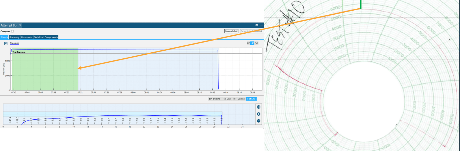
API Std 53 requires that a low-pressure test shall pass between 250-350 psi. The images in figure 1 demonstrates the CCR test passed at 409 psi. The lack of detail from the CCR does not clearly demonstrate small discrepancies with the regulations and leaves the results open to interpretation.
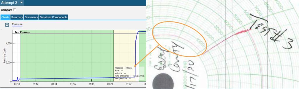
Illustrated in the Figure 2, the test passed the approved criteria at minute 10 (SureTec). The test was then held out for an additional 21 minutes on the CCR. This additional time was caused by the subjective review by the tester.
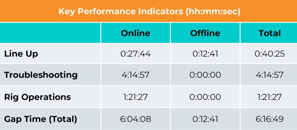
The below table (Figure 3) provides details on gap time analysis. Understanding and tracking these gap times helps drive efficiency and lessons learned.
IPT partnered with a global operator to drive integrity and assurance standardization across its business units by introducing digital pressure tests utilizing the industry-leading technology software, SureTec.
IPT’s solutions provided objective, tamper-proof and auditable results for well barrier integrity validation. Process and performance opportunities were easily identified that were used to make sustainable changes to programs and standards.
During the implementation of SureTec, our client said, “I’m so happy we are making the switch. Using this digital tool and being involved in the digital transformation is critical for assurance and driving efficiency.”
Let IPT be a part of your digital transformation and benefit from the application of digital data to drive efficiency and improve assurance.
Effective BOP Stump Testing is a critical to eliminating unplanned stack pulls. A significant portion of the industry still uses very loose testing criteria during these tests that can result in components lacking integrity to be deployed.
This article describes how IPT’s patented advanced algorithms called, Trend Analysis were able to identify previously undetectable leaks. We present two examples that demonstrate its ability to identify subtle leaks that alternative digital pressure testing products would not be able to identify during critical BOP Stump tests.
To further enhance the leak detection capability of SureTec, IPT developed the patented Trend Analysis algorithms to eliminate the scenario where a low rate of change in the pressures can have a degrading trend indicative of a small and subtle leak. IPT’s layered and advanced algorithms are customizable and configurable to meet client’s objectives (Figure 1).
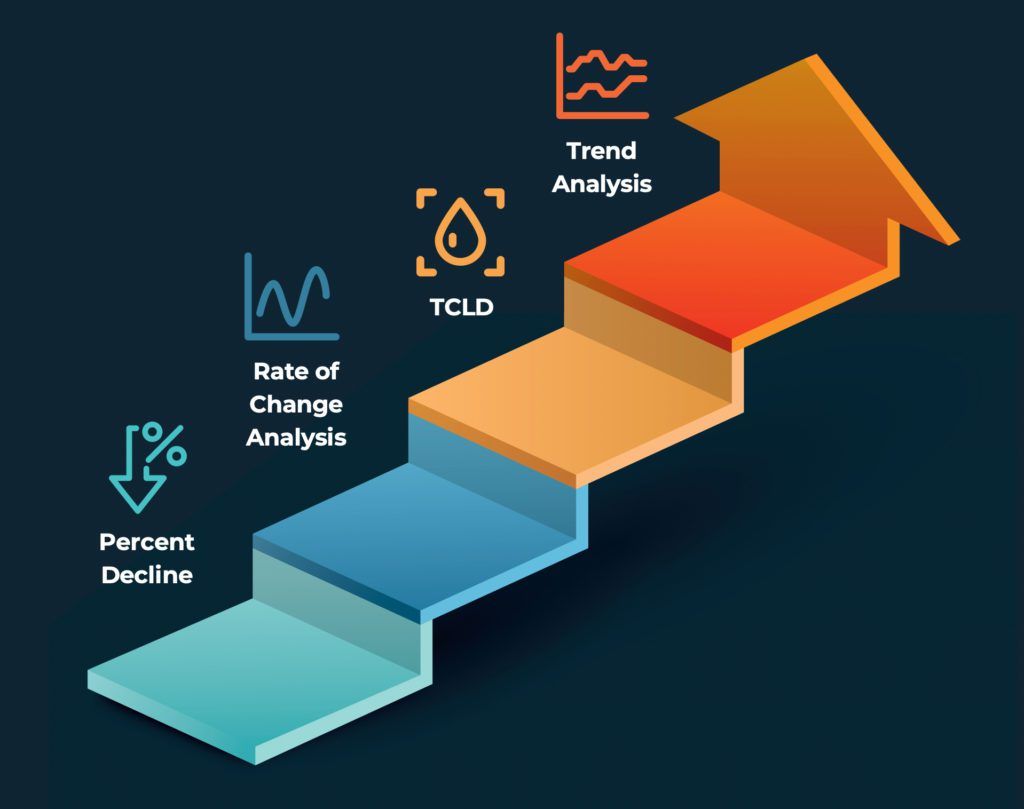
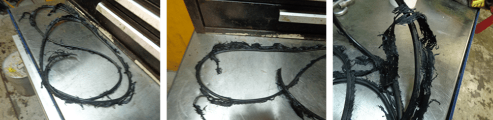
SureTec’s Trend Analysis can find small leaks during BOP Stump tests so they can be fixed on the rig to avoid an unplanned BOP stack pull from the seafloor potentially costing millions of dollars. In one example, IPT’s Field Advisors ran a Stump test using SureTec on a rig in the Gulf of Mexico. Trend Analysis failed the test because the ROC values were not improving. At first, the operator and contractor thought that Trend Analysis needlessly failed the test. After inspecting the BOP, the rig crew found the leak on the Lower Pipe Ram’s outer door face seal (Figure 6).
In another example, an IPT Field Advisor and a subsea engineer (SSE) were witnessing a Stump test using Trend Analysis. When testing the Upper Pipe Ram (UPR) against 7” drillpipe, it became apparent to the Field Advisor that Trend Analysis was not improving, indicating a leak. The SSE was not convinced there was a leak; however, IPT’s Field Advisor was adamant that the UPR had a leak or a valve had been left open. Upon inspection of the BOP, the subsea crew found a leak in the UPR. Parts were flown out the next morning to repair the UPR. After the seals were replaced, the UPR was retested against 7″ and 4.5″ drillpipe and it subsequently passed Trend Analysis.
The results of the tests were gathered by the operator and presented to both parties (Figure 3). According to the major operator, tests performed using SureTec were 20% faster than the competitor’s tests. In addition to faster test validation, IPT provided a high level of integrity assurance using SureTec’s patented algorithms.
Trend Analysis can prevent costly and potentially catastrophic events by detecting leaks during critical pressure tests on BOP components. IPT’s Advanced Leak Detection Algorithms are available in the Standard, Advanced, and Premier tiers of SureTec. Contact us today to learn how our advanced analysis can improve your safety and operational efficiency.