
Some digital pressure testing methods used in the oil and gas industry rely on predictive early data trends to draw conclusions about future performance. While these approaches may appear sophisticated, they often depend on assumptions that can be misleading. In safety-critical operations, the consequences of being wrong can be very dangerous.
At IPT Global, our approach is grounded in physics: how equipment actually behaves under pressure and an array of thermal variables. Our SureTec® PressureTesting Solution focuses on measurable system behavior rather than early-time trends and predictions, which provides greater assurance, protecting people, assets, and the environment.
During well control equipment pressure testing, a pressure decline can result from three distinct causes:
Why is this a problem? Because all three occur at the same time, and their combined effects appear as a single pressure curve making interpretation more challenging than it first appears.
Many digital pressure testing tools attempt to determine a pass or fail by observing how pressure decline slows over time. However, thermal and elastic effects naturally dominate early behavior and always attenuate. This early stabilization can create the appearance of improvement even when a real leak is present.
In short, early-time prediction alone does not confirm integrity, but rather introduces uncertainty at precisely the point where certainty is required.
Rather than predicting what might happen, IPT Global’s PressureTesting Solution models how a leak-free system should behave. We account for normal pressure changes caused by temperature and equipment expansion, establish a physics-based fingerprint for a healthy system, and evaluate subsequent tests against that baseline to identify true integrity failures.
Our focus is on delivering accurate, objective digital pressure testing results. In practice, that means fewer assumptions and clearer answers during the test itself. Instead of relying on trend-based prediction, we ask a more fundamental question: Does the observed behavior match that of a leak-free system?
A major offshore operator evaluated IPT Global’s physics-based PressureTesting Solution against a competing predictive pressure testing solution using real subsea BOP test data, including tests with confirmed visible leaks.
IPT Global correctly identified every known failure. The predictive solution, however, incorrectly passed multiple tests, including some with confirmed visible leaks.
A false pass, indicating equipment integrity when a failure exists, can expose operations to safety risks, environmental damage, unplanned downtime, and reputational harm.
Ultimately, when people, assets, and the environment are on the line, uncertainty should never be mistaken for insight. Physics-based analysis replaces assumption with understanding and delivers the confidence that safety-critical decisions demand.
Data integration, the process of unifying information from multiple sources, is essential for effective well integrity management. This includes gathering and analyzing data from various sources, such as well design and construction, continuous monitoring, and well integrity testing. By integrating data across all phases of a well’s lifecycle, operators gain a holistic understanding of well health, enabling more informed decision-making and improving safety and performance. This article explores how data integration optimizes well integrity management and the benefits it offers for optimizing well operations.
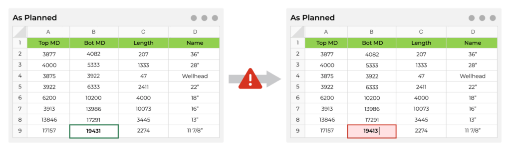
Wellbore data is often used across multiple systems, including well integrity management systems, but is typically entered manually into separate applications. For example, the same data might be used to generate wellbore schematics, barrier diagrams, and test plans—three distinct applications that don’t interact with one another. When wellbore data, such as casing, transitions from “as planned” to “as built,” it must be manually updated in one application (e.g., a spreadsheet) and then reentered into another application for the barrier diagram. This process repeats every time the data changes. Similarly, when a well schematic is used to develop a wellbore integrity test plan prior to operations, it must be updated with as-built data, and then the test plan needs to be revised accordingly. Additionally, wellbore data across different systems or regions may have varying structures or Units of Measurement (UoM), which can lead to issues such as calculation errors and data misinterpretation. This creates inefficiencies and increases the risk of inconsistencies whenever updates occur.
Integrating well integrity data unifies these workflows into a single application, enabling seamless communication of schematic and test plan changes while automating test planning and barrier management processes.
One of the leading causes—as much as 50%— of non-productive time (NPT) is the mechanical failure of equipment such as BOPs, subsea trees, and wellheads. There are more than 100 hydroelectric valves and regulators inside a BOP and historically, little was known about the fatigue life of these components. This lack of insight resulted in BOP manufacturers arbitrarily replacing as much as 25% of the BOP stack each time it underwent scheduled maintenance – an approach designed to prevent breakdowns but often resulting in excessive and unnecessary part replacements.
One of the most significant advantages of data integration in well integrity management is the ability to leverage predictive analytics for proactive maintenance and risk mitigation. By analyzing historical data and monitoring real-time data from multiple sources, operators can reduce the likelihood of well integrity issues that could lead to costly downtime or safety incidents. For BOPs, condition-based monitoring (CBM) allows potential problems to be predicted, based on the remaining service life of individual components. This enables BOPs to remain subsea longer without being retrieved to the rig for premature repairs. CBM also allows operators to schedule maintenance at optimal intervals, minimizing unnecessary NPT while ensuring equipment remains in reliable working condition. As a result, unplanned maintenance and production disruptions are reduced, contributing to improved operational safety and efficiency.
Operators must comply with strict regulatory standards and recommended practices for well integrity monitoring and reporting. Non-compliance can lead to fines, operational delays, or even well shutdowns. Data integration ensures that operators meet regulatory requirements more efficiently and comprehensively. By consolidating production data into a unified system, operators can generate regulatory reports more quickly, reducing the time and effort involved in manual data collection. This automated reporting process minimizes the risk of human error and ensures that all relevant data is captured accurately. Additionally, integrated data systems offer real-time updates on well integrity status, enabling operators to respond swiftly to emergencies and remain compliant.
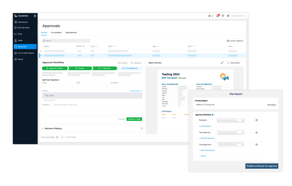
Well integrity management requires close collaboration between various teams, including engineers, operations staff, and safety personnel. Effective communication between these groups is critical for promptly identifying and resolving well integrity issues. When data is spread across multiple applications, teams often rely on phone calls and emails to share updates, which can lead to delays and miscommunication. Data integration addresses this challenge by providing all teams with real-time access to the same information. This unified data view eliminates silos, enabling teams to collaborate more effectively and identify potential issues sooner. Additionally, integrated data systems allow for single updates across platforms, ensuring that all teams can make informed decisions using the most current data without needing to switch between multiple sources.
The digital transformation in the oil and gas industry is progressing rapidly, with companies increasingly leveraging technologies such as artificial intelligence (AI), machine learning, and the Internet of Things (IoT) to optimize well operations. Central to this transformation is data integration and the preparation of data for AI analysis, which forms the foundation for applying advanced analytics to well integrity data. For example, AI-powered analytics can process vast amounts of historical well integrity data to uncover trends and anomalies that humans may overlook. These insights can then be used to inform maintenance strategies, optimize well operations, and improve safety.
Data integration is crucial for effective well integrity management. By consolidating information from well design, construction, and continuous monitoring, operators can enhance their understanding of well health, leading to more informed decision-making and improved safety. Data integration enables the use of predictive analytics to anticipate equipment failures, mitigate risks, and reduce downtime. It also supports the development of unified applications that consolidate, integrate, and automate well integrity management workflows. Moreover, data integration simplifies regulatory compliance by enabling faster and more accurate reporting and incident response.
Collaboration among teams is significantly improved as all members gain access to real-time data, breaking down communication barriers. As the oil and gas industry increasingly embraces AI and IoT technologies, data integration will continue to be essential for optimizing operations and ensuring safety.
At IPT Global, we are dedicated to helping organizations tackle data integration challenges. Our team of experts is ready to assist you in streamlining your data processes and maximizing your operational potential. Contact us today to discover how we can support your data integration needs!
Ensuring well integrity throughout a well’s lifecycle is essential for maintaining safe and efficient operations in the oil and gas industry. Effective annular casing pressure (ACP) management is key to preventing problems with well barrier elements (WBEs) such as casing leaks, sustained casing pressure (SCP), and subsea safety valve (SSV) malfunctions. Implementing a structured ACP monitoring and reporting system ensures transparency during operational handovers and provides an auditable record for forensic analysis if required. Without effective integrity management, operators risk unnecessary well shut-ins and costly interventions.
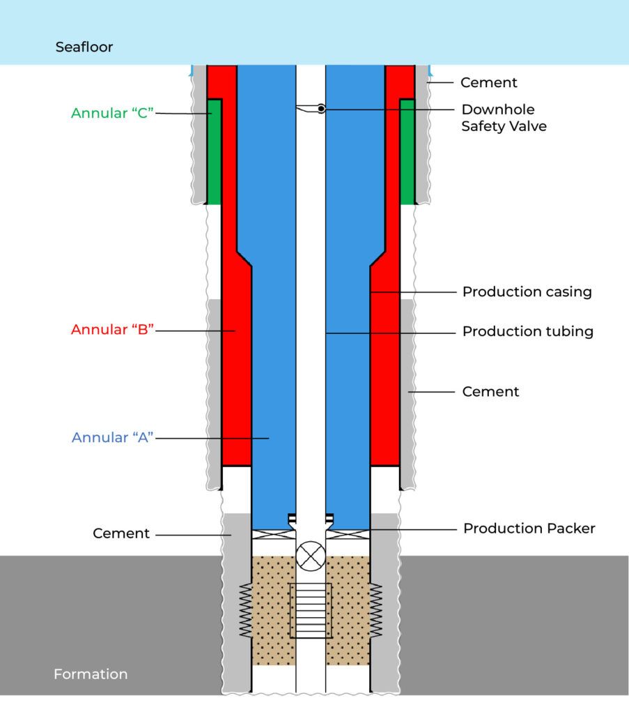
The illustration below shows the standard designations for the “A”, “B”, and “C” annuli in a subsea well. The “A” annulus is the void between the production tubing and the smallest casing string while the “B” and “C” annuli are the voids between the successive outer casing strings.
The sealed annuli contain trapped fluids that later become heated by the high flow rate of formation fluids during production. The hotter fluids expand, causing an increase in the annulus pressure on the well. Eliminating any pressure fluctuations due to thermal effects, a pressure change in the “A” annulus is an indication of a leak. The pressure measured at the wellhead in the “A” annulus, or in the other annuli that terminate at the wellhead, is called the annular casing pressure (ACP).
Annular casing pressure (ACP) is a primary indicator to detect leaks within the barrier envelope. Deviations in pressure within the “A” annulus may indicate leaks in one of the barrier elements, excluding the Downhole Safety Valve (DHSV). Troubleshooting involves adjusting pressure in the adjacent “B” annulus and the production tubing to identify the failing barrier element. The rate of pressure change can help assess well integrity risk levels.
A production packer anchors the tubing string and isolates the “A” annulus from both the formation and the tubing’s interior. Leaks in these seals or any connections can lead to SCP within the “A” annulus. For subsea wells, only the pressure in the “A” annulus can be monitored and bled down, while surface and land wells allow monitoring and bleeding at the wellhead.
API Recommended Practice (RP) 90-1 identifies three sources of annular casing pressure:
Of the three pressure sources, SCP is the only one that will rebuild once bled off. SCP may result from communication with a pressurized formation or from a barrier that inadvertently creates a flow path. The following potential communication paths can affect the “A” annulus and the “B” and “C” annuli.
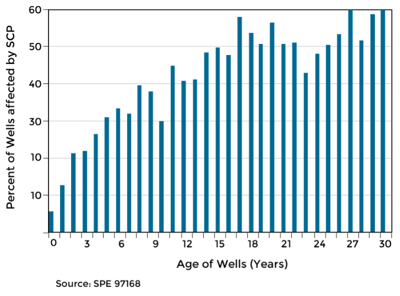
The occurrence of SCP tends to increase throughout a well’s lifecycle, from drilling to abandonment. Continuous monitoring of ACP is therefore considered best practice.
API RP 90-1 Section 9 outlines recommended procedures for ACP in offshore wells. It highlights the importance of equipping all accessible annuli with the ability to monitor pressure, perform bleed-offs, and inject fluids when necessary. Initial pressure testing should be conducted to establish baseline values and identify any existing ACP resulting from operational conditions.
IPT Global’s SureTec® PressureTesting solution, including the TestEngine module, supports this process by helping operators establish and track baseline pressure values consistently across wells.
Regular monitoring is essential, with operators responsible for setting a minimum frequency to ensure pressure remains within diagnostic limits. The section distinguishes between operator-imposed and thermally induced pressures and emphasizes the need for close observation following any operational changes.
When SCP is detected outside of acceptable thresholds, the frequency of monitoring should be increased. For inaccessible annuli, a formal risk assessment is required to determine the feasibility of restoring monitoring capabilities and to assess the implications of any pressure sources.
Overall, this section offers a comprehensive framework to support safe and effective ACP management and ensure long-term well integrity.
Annular casing pressure management is a critical component of well integrity management. By understanding the causes of ACP fluctuations, implementing best practices, and leveraging solutions like SureTec PressureTesting, operators can proactively prevent integrity failures, minimize costly interventions, and enhance operational safety. Standardized reporting, automated data collection, and routine diagnostics ensure regulatory compliance and long-term sustainability. Investing in a structured ACP management strategy ultimately protects assets, personnel, and the environment. For more information on how like SureTec PressureTesting can enhance your well integrity management, contact IPT Global today.
Well integrity is crucial to the safety and success of plug and abandonment (P&A) operations, including well decommissioning. P&A operations involve the installation of barriers to seal the wellbore and prevent migration and leakage of formation fluids in perpetuity. Well barrier failure during the decommissioning process could lead to environmental damage, harm to local communities, and significant legal and financial consequences for the operator. The purpose of this article is to describe the importance of well integrity in offshore P&A operations and how to assure well integrity through testing and verification of complete barrier systems.
Operators plug and abandon a well when it is no longer profitable to produce or useful, as with an injection well. The primary objective of the P&A process is to ensure the well’s integrity by creating a permanent barrier system that isolates the wellbore from the formation and prevents fluid migration into groundwater zones or to the surface.
The P&A process begins with assessing the history and condition of the existing well barrier elements and developing a plan to install and verify additional barriers that are required. The operator confirms that the plan meets regulatory requirements and industry guidelines and selects a P&A service provider to perform the P&A operations. Once on site, the service provider removes any wellbore debris or obstructions from the wellbore before logging the well to assess its condition and identify any potential subsurface leaks or hazards.
The service provider places cement and mechanical barriers, such as bridge plugs and cement retainers, at predetermined intervals to isolate zones and prevent fluid migration from the formation. A common well abandonment technique is to place cement plugs on top of mechanical plugs. Cement barriers also provide structural support for the casing, prevent corrosion, and structurally reinforce the wellbore. Cement plugs are used in open hole applications and across liner tops. Physical depth tagging may be performed to confirm plug location.
Next, the service provider verifies the integrity of the barriers using pressure testing and cement bond logging. The contractor may also use diagnostic tools, such as temperature surveys and noise logging, to detect any potential channels or leaks in the cement barriers. After verifying barrier integrity, the contractor cuts and removes the wellhead and any remaining wellbore components, such as production tubing and casing, in accordance with company policy and local regulations. The contractor also retrieves any equipment from the seabed, such as production trees and control systems, and clears the site. Finally, the service provider compiles all documentation of P&A activities into a report for handover to the operator.
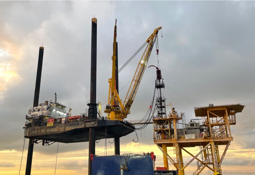
Well integrity is critical to P&A operations regarding regulatory compliance, safety, and environmental considerations. Operators must adhere to regulatory requirements and industry standards to ensure well integrity, and they must use responsible practices to mitigate potential hazards that threaten health, safety and the environment.

All regulatory agencies require integrity testing of well barrier components. For example, in the United States, the Bureau of Safety and Environmental Enforcement (BSEE) and the Environmental Protection Agency (EPA) provide regulations and guidelines for P&A operations. In the Norwegian petroleum industry, the NORSOK D-010 standard defines the minimal functional requirements for well design, planning and execution with the aim of maintaining well integrity throughout the life cycle of the well. In the UK, the North Sea Transition Authority (NSTA) and Health and Safety Executive (HSE) regulate these activities.
Meeting regulatory requirements and obtaining the necessary permits for P&A activities can be challenging, as regulations may differ across jurisdictions and evolve over time. Operators must obtain necessary permits and engage with regulatory authorities throughout the P&A process. This will ensure compliance, reduce risks, and manage changes to approved programs that may be necessary during operations.

Plugged and abandoned wells with compromised well integrity can expose the environment to a variety of air and water pollutants. The release of gases, volatile organic compounds (VOCs), or hazardous air pollutants can occur if proper controls are not implemented during and after P&A operations. The migration of formation fluids into groundwater, surface water bodies, or marine environments may impact water quality and disrupt terrestrial and marine ecosystems. Fluid migration across ineffective barriers may create future operational challenges by creating shallow gas or over-pressured zones at unexpected depths.
Well integrity ensures that the paths between different subsurface formations are sealed so that fluids and gases remain confined within their original formation zones. This prevents the risk of uncontrolled fluid migration that could contaminate soil, groundwater, surface water, or marine environments. A quality program and supporting integrity documentation can demonstrate the effective plug and abandonment of assets and may be useful in any investigation or troubleshooting later.
The following is a summary of best practices for ensuring well integrity during and after P&A operations.
Planning P&A activities during the well design phase identifies cost-effective solutions based on well complexity and facilitates smoother execution with a pre-defined plan for abandonment. Early planning also enables knowledge transfer and the handover of critical documentation.
Assess the condition of the well and thoroughly clean the wellbore to remove any obstructions that can interfere with the cement bond integrity and other plugging operations.
Adhere to applicable regulations and guidelines, obtain necessary permits, and engage with regulatory authorities throughout the P&A process to ensure compliance and reduce risks.
Developing well abandonment plans that consider the specific characteristics of the well, reservoir, and surrounding formations is crucial for selecting appropriate techniques and materials to achieve long-term well integrity.
Additional mechanical barriers, such as bridge plugs or cement squeeze operations, may be installed above or below the primary cement barrier to enhance well integrity. All plug depths should be set for the purpose of isolating a zone or protecting a zone based on well conditions and geometry.
Implement rigorous quality control measures, including cement bond logs and pressure testing to independently test and verify barrier integrity (described in the following section).
Compile reports of all activities, including well logs, pressure test results, cement bond logs, and other relevant data.
Regularly monitor and observe abandoned wells to detect any signs of potential leakage or integrity failure to enable timely remediation actions.
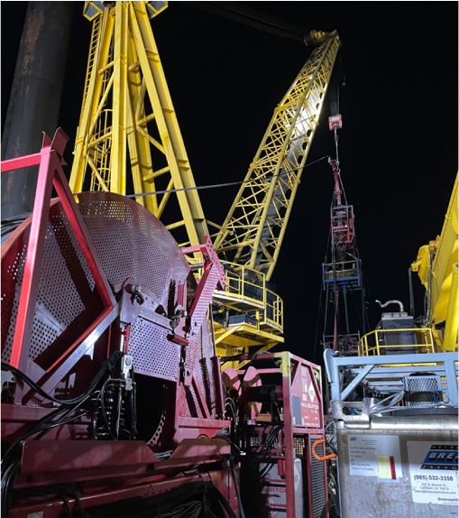
The consequences of a barrier integrity failure are considerable, impacting public health, safety, and the environment, and it can lead to legal and financial penalties and damage to reputation. The integrity of a barrier is not assured until it has been tested and verified using the technologies described below.
Well integrity is not established by individual barrier components but on the collective performance of all components in the wellbore. The operator may use data collected during well construction or run a new cement bond log using a sonic tool that measures the bond quality of the cement to the casing and to the formation. This provides insights into channels or voids in the cement sheath that can act as potential pathways for fluid migration. This information is vital in targeting specific zones for placement of cement plugs and mechanical barriers. A common abandonment technique is to place a cement plug on top of a mechanical plug at multiple zones in the wellbore. Cement plugs are also used in open hole applications and across liner tops.
All local regulations require cement barriers to extend across the full cross section of the wellbore. The best methods to validate a cement plug placement are the drill pipe weight test and pressure testing. The main advantage of the drill pipe weight test is that it is used to tag the top of the cement in wells with high angles or poor hole conditions to confirm that the plug is at the required depth. However, the weight test is less stringent than pressure testing when measuring the cement plug seal effectiveness.
Pressure testing is the most effective method of barrier verification. It is used to verify the integrity and effectiveness of the collective barrier system based on specific criteria specified by the operator. Pressure testing is also typically performed on a cement plug set above a plug that was tagged. A predetermined pressure is applied that exceeds the anticipated pressure differentials that the barriers are expected to encounter. Positive or negative (inflow) tests are used based on the direction of expected flow. The pressure is analyzed for a specific duration against the operator’s criteria to objectively determine if the barrier system passes or fails.
IPT provides a comprehensive digital solution for planning, testing, and reporting integrity tests on well barrier systems during P&A operations. Digital pressure testing allows more efficient and accurate integrity assurance because it uses objective criteria to determine whether a pressure test passes or fails.
Qualified professionals should be engaged to carry out monitoring and inspections to properly assess the condition of P&A wells. These professionals should have experience in well integrity management, regulatory requirements, and be able to interpret inspection results accurately.
IPT’s team of subject matter experts provides barrier integrity verification, tracking, and consultation services to support your well integrity program.
The specific steps and techniques to maintain well integrity vary but the means to assure the integrity of the well are constant. IPT’s products and services test and verify the integrity of the entire well barrier system during all phases in the life cycle of a well including plug and abandonment. Contact us to learn more about how IPT’s products and services can ensure the success of your P&A operations.
Well integrity is determined by the reliability of well barrier elements (WBEs) to prevent the uncontrolled release of fluids from an oil and gas well into the environment. The consequences of the loss of well barrier integrity can be severe, ranging from environmental damage to fatalities. Sustaining well integrity throughout a well life cycle is critical in minimizing risk due to failed WBEs. However, a well’s operating conditions or utilization may change as the well ages, adversely affecting the integrity of critical WBEs. It’s difficult to maintain consistency in well integrity over the years through knowledge transfer and documentation handover among teams. IPT provides a centralized cloud-based platform that manages well integrity data and regulatory compliance through each phase of a well’s life, including drilling, completion, production, workover, intervention, and plug and abandonment.
During drilling and completion, improve well integrity management by designing, planning, testing, and reporting barrier verification test results in one integrated well integrity life cycle management platform for total assurance.
Operators use a cloud-based application to build schematics, wellbore diagrams, and test plans for drilling and completion. The application generates a standardized, detailed test plan report including schematics, criteria, and complete documentation of surface and subsea components to be tested for each well integrity test. The tests plans can be digitally routed for approval and securely stored in the cloud using the Assurance Workflow tool.
The Assurance Workflow tool allows signatories to download and review drilling and completion test plan reports, and it simplifies the gathering of digital approvals via mobile devices. It streamlines collaboration and communication by rerouting rejected test plans and test reports for modifications and final approval.
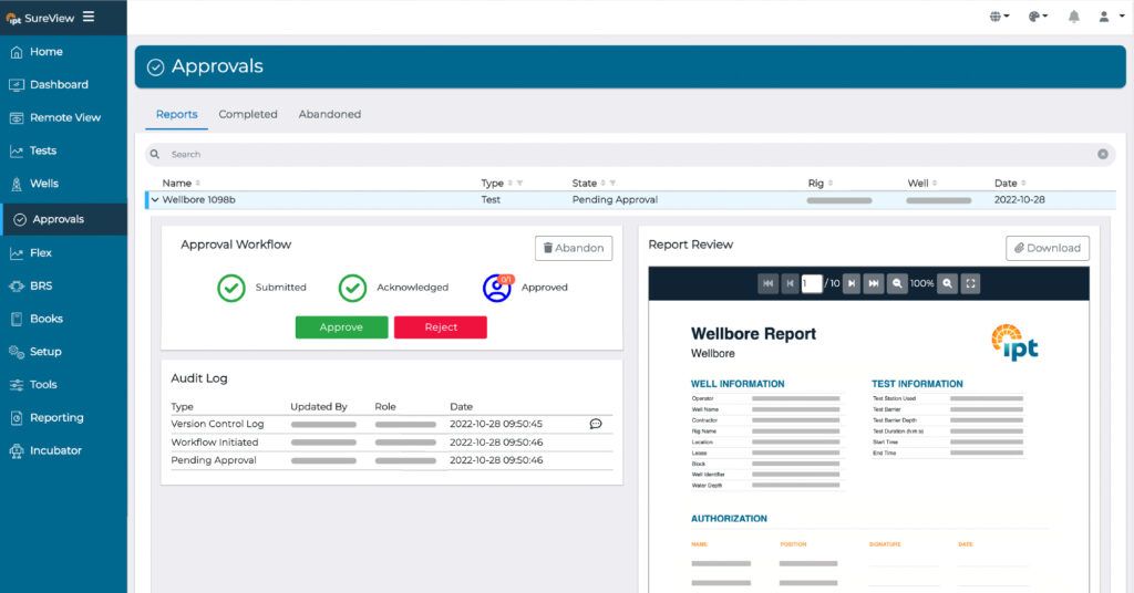
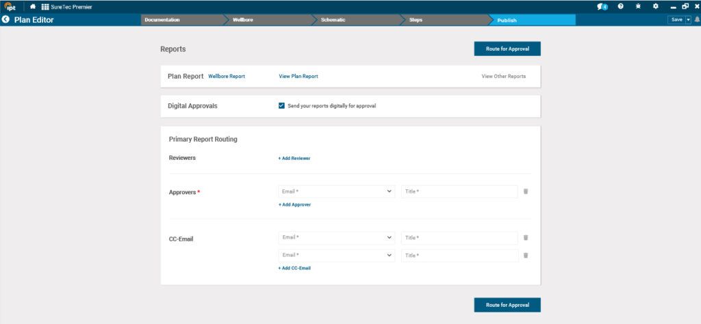
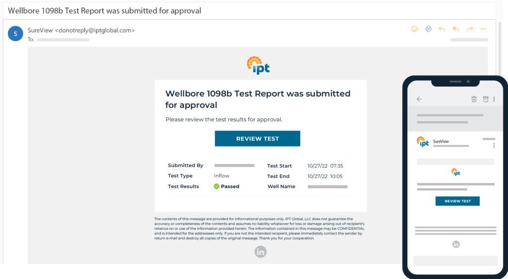
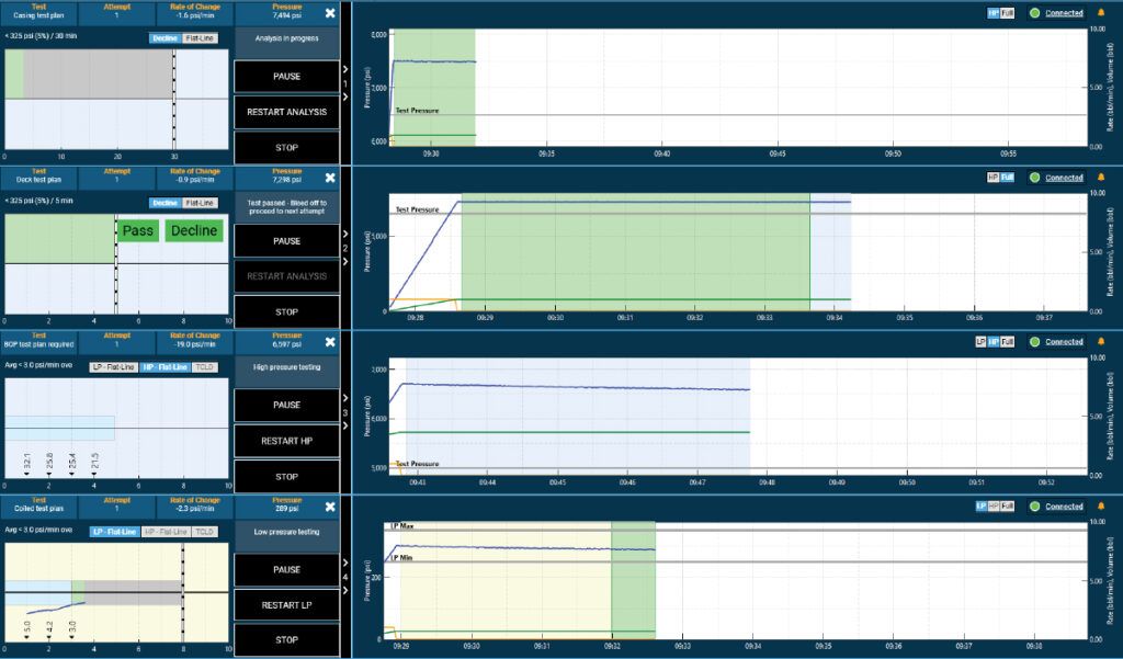
Performing accurate, comprehensive, and efficient integrity tests during drilling and completion is a challenge in high-pressure, high-temperature environments. It requires comprehensive well integrity management software and effective collaboration between the operator and service company performing the tests. An accurate, consistent, and transparent methodology is necessary for validating and managing the integrity of WBEs. IPT’s patented algorithms—including Thermally Compensated Leak Detection evaluate pressure test data based on objective criteria and definitively confirm whether an integrity test passed or failed. Reports for completed tests are automatically uploaded to the cloud and routed for digital approval using the Assurance Workflow tool. The cloud-based platform also provides remote viewing of active tests from anywhere in the world, test data archival and retrieval, and advanced data visualization analysis.
IPT collaborates with operators and contractors on-site and remotely through its industry-leading experts. Field Service Advisors provide on-site integrity test coordination and optimization. Engineers perform post-test reviews to ensure that all components are properly tested. Real-Time Operations Engineers & Advisors (RTOAs) verify that test reports are published properly to assure the traceability of all integrity tests for hand off to the production team. BOP Compliance Surveyors provide third-party equipment inspection and auditing using industry recommended survey and inspection practices.
Blowout preventers (BOPs) serve as a critical secondary barrier during drilling. The challenge for drilling contractors and operators is to know when to repair or replace BOP components to minimize non-productive time (NPT) due to component malfunction or failure. Regulations require operators to periodically pressure test and function test BOP stack components to ensure well integrity. Contractors perform weekly function tests to actuate the rams and annular preventers to ensure they will operate properly in an emergency. The actuation duration and volume of hydraulic fluid required are important indicators of the health of critical BOP components.
IPT engineers monitor and analyze BOP pressure tests, BOP function tests, maintenance, and failure data to gain insight into when and why failures occur. Engineers use data visualization to spot trends in pressure and function test data so that contractors can repair and replace BOP components, when necessary, rather than on an arbitrary schedule as commonly used.
Production has a different set of challenges to maintain well lifecycle integrity while optimizing production. These challenges include complex physical and chemical process changes that occur in the wellbore and surrounding formations. Adding to this complexity, aging oil and gas wells become more prone to corrosion, erosion, and other forms of wear and tear that can compromise well integrity. The production team must decide when to intervene and extend production or retire a well that is no longer safe or economically viable.
The centralized well lifecycle integrity management solution ensures complete documentation handover to the production team. It gives the team access to WBE integrity data and reports for transparency and compliance. It also allows the team to compare integrity data with other wells to identify potential issues before they become major problems.
Integrity testing of well components during light and heavy (workover) interventions presents different challenges for well lifecycle integrity management than testing during well construction. As interventions have a shorter duration of a few weeks, component integrity tests are carried out more frequently compared to the construction of a well. Many offline integrity tests are performed simultaneously on the deck of the intervention vessel to eliminate delays once the crew connects to the well.
Multi-testing capability enables the crew to perform integrity tests thoroughly and efficiently to avoid delays in critical path operations that would be costly for both the intervention service company and the operator. After the intervention is completed, there is traceability of all well integrity tests to hand off to the production team and for compliance with local regulatory bodies.
Compliance regulations that govern plug and abandonment regulations can vary across jurisdictions, which makes compliance challenging for operators with international assets. Operators must comply with these regulations to ensure safe and environmentally responsible operations. Regulations typically cover a range of areas, such as casing and cementing requirements, pressure testing procedures, and monitoring and reporting requirements.
A critical aspect of compliance with plug and abandonment regulations is the need for integrity management of well barrier elements (WBE). Well integrity management software can be used to provide historical data on each WBE. This data can help operators identify any potential issues that may arise during the abandonment process, such as defective equipment or oil leaks. All P&A activities can be tracked and documented with integrity management software providing a comprehensive record of the operation ensuring compliance with regulations are met. By having this data, operators can take steps to ensure that the well is abandoned safely and mitigate risks.
Ensure the reliability of well barrier elements over the entire well life cycle. Implement IPT’s centralized cloud-based platform to manage well integrity data, regulatory compliance, and integrity testing through each phase of the well’s life cycle. With IPT, you can improve well integrity management during drilling and completion, maintain BOP integrity, optimize production while ensuring well integrity, and comply with plug and abandonment regulations. Act now to minimize risk and ensure the safety and sustainability of your operations. Contact us for more information on managing integrity throughout the well lifecycle.
Marine Well Containment Company and Helix Well Containment Group (MWCC and HWCG) are skilled in maintaining and developing capping stacks. IPT partners with these consortiums to validate the capping stack integrity prior to deployment to prevent oil leaks. IPT provides rapid, efficient, and transparent capping stack testing that reduces testing time and ensures reliable deployment. Pressure tests can be viewed from anywhere with IPT’s cloud-based application creating transparency for operators, contractors, and regulators alike.
A capping stack is a device used to control the flow of oil and gas from a well in the event of an emergency or unplanned release of hydrocarbons.
The capping stack can be placed on top of a wellhead. The capping stack contains a number of valves and control systems that can be operated remotely to shut off the flow of oil and gas.
In the event of a well blowout or other emergency, a capping stack can be deployed to contain the release of hydrocarbons and prevent further damage to the environment.
Since the Deepwater Horizon Incident in 2010, regulations have been put in place to require the availability of capping stacks as a response measure in case of a catastrophic incident.
Capping stacks have been developed with advancements in technology and increased awareness of the importance of well control and blowout prevention.
However, the use of capping stacks gained significant attention following the Deepwater Horizon oil spill in 2010. The spill was one of the worst environmental disasters in history, sending millions of barrels of oil into the Gulf of Mexico. The spill continued for 87 days before the well was finally capped.
In response to the Deepwater Horizon incident, the oil and gas industry, government agencies, and regulators placed increased emphasis on well control and blowout prevention. The first subsea capping stack was deployed in 2011, as a response to the Deepwater Horizon oil spill in the Gulf of Mexico. The capping stack was designed and built by a consortium of oil and gas companies, including ExxonMobil, Chevron, ConocoPhillips, Shell, and BP, along with service companies, mainly Trendsetter Engineering, through a working partnership with the US government.
The subsea capping stack was specifically designed to be deployed in deepwater environments, where traditional capping stacks were not effective. The device was capable of withstanding high pressures and temperatures and could be deployed using remotely operated vehicles (ROVs).
The subsea capping stack was tested and validated in a series of simulated blowout scenarios before being deployed to the site of the Deepwater Horizon incident. The device was successfully used to cap the well, bringing the oil spill under control after 87 days of uncontrolled release.
Since then, subsea capping stacks have become a required component of offshore drilling operations, with regulations mandating their availability in case of emergencies. The development and deployment of subsea capping stacks have improved the ability to respond to well blowouts and other emergencies, minimizing the impact on the environment and human life.
The US Bureau of Safety and Environmental Enforcement (BSEE) published new regulations in 2016 that require operators of offshore drilling operations in US waters to have access to well capping systems capable of controlling the flow of hydrocarbons in the event of a blowout. These regulations have led to increased development and deployment of capping stacks.
There are now over a dozen capping stacks spread geographically across areas ready to be deployed at a moment’s notice. The two Gulf of Mexico consortiums, Marine Well Containment Company and Helix Well Containment Group are comprised of highly skilled employees, engineers and contractors that maintain and develop capping stacks to be deployed at a moment’s notice.
In any emergency situation, rapid response is critical to minimizing the impact of an incident. Great emphasis is placed on preparedness and response planning, including the pre-positioning of equipment and the training of personnel in well control and emergency response procedures. Not all well containment scenarios are the same, and many factors could influence the necessary response. If a capping stack is needed, it must be tested prior to deploying subsea. This includes a pressure test to validate the integrity of the capping stack to prevent an oil leak. IPT provides well integrity assurance through the use of advanced algorithms to detect leaks. This is applied on capping stacks to determine the integrity of the capping stack prior to deployment. IPT provides clear and actionable results in real time that can be broadcasted on IPT’s cloud-based application to anyone in the world.
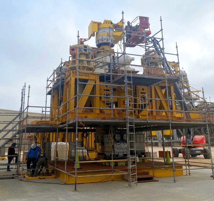
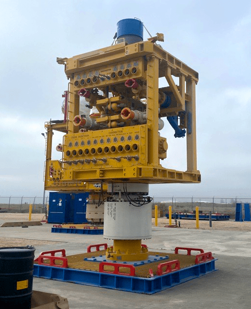
IPT provides pressure testing assurance with the use of Thermally Compensated Leak Detection (TCLD) analysis which compares the natural thermal pressure decay to determine if there is a leak. IPT’s TCLD provides more efficient pressure testing of capping stacks. Prior to March 2023, Trendsetter Engineering was relying on the traditional method of pressure testing, however IPT worked with Trendsetter to create a pressure test procedure with TCLD. As a result, IPT was able to reduce the amount of time on pressure by two hours. This time savings also aided maintenance operations where pressure testing went from taking two days to only one.
Because Capping Stacks are pressure tested prior to deployment, every minute counts in reducing the harm to the environment.
As an industry we strive for our commitment to protecting personnel and the environment, we hope to never need to use a capping stack to stop an oil spill but are prepared to deploy one at a moment’s notice and have made large strides in reducing the response time. IPT has assisted MWCC & HWCG in reducing the time required testing capping stacks and providing an industry leading integrity assurance.
Pressure test may be broadcasted through IPT’s cloud base application. Consortium members and regulators alike are able to witness the capping stack testing in real time, anywhere in the world. This creates transparency where operators, contractors and regulators can witness and collaborate during testing in real-time regardless of their location.
IPT collaborates with the consortium through the use of onshore maintenance testing and system integration testing prior to the deepwater deployment drill. IPT draws on extensive industry experience to advise on testing criteria for this unique type of well control equipment.
IPT is proud of working in the oil and gas industry to help demonstrate the confidence a capping stack can be reliably deployed, and integrity tested using IPT’s software. Contact us to learn more about our capping stack testing capabilities.
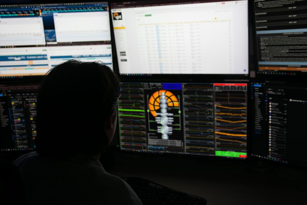
IPT’s real-time BOP monitoring (RTM) allows for improved data transparency, analysis and data-driven decision making. This data also bolsters rig safety by providing instant access to real-time and historical BOP data. Ultimately, data streamed from the BOP control systems will enable predictive and condition-based maintenance.
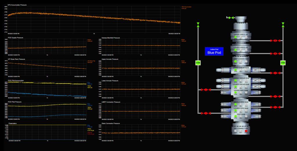
IPT’s RTM solution product shows clear, BOP visualizations to ensure close correlation between the panels and gauges that rig personnel are accustomed to seeing.
Live BOP Stack: Real-time view shows the status of the BOP stack by displaying the components along with color indicators showing the state of each component. In this view, the user can also see key pressure, temperature and flowmeter values.
Live Pressures: Real-time view provides an easy-to-read visual of key pressures during operations. The user has the option to view the indicators in radial or linear gauge form.
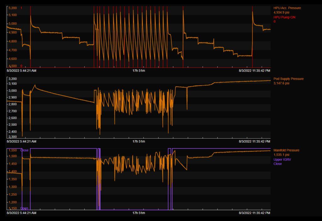
Live Database and Visualizations: Real-time view gives complete access to all data recorded on the data logger located on a rig. It allows the user to graph and trend up to 10 values in a live view as well as go back to evaluate historical data.
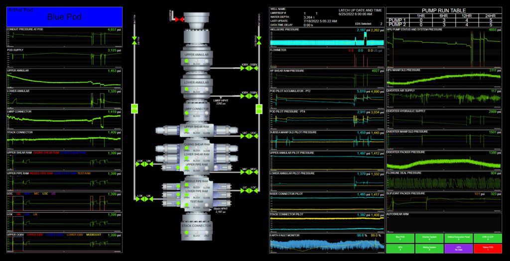
Rig-Side Function Test Management: This digital solution tracks rams and annular function testing. It provides real-time assurance of component states and control systems in a user-friendly interface. Clients can utilize function test management with our digital approval management platform.
Data integrations (APIs): We also offer the ability to send data directly to our client’s enterprise data system via our secure API connector, allowing our clients to integrate our data within their decision-making matrix.
Experienced and trained subject matter experts are the foundation of our real-time monitoring service. Our BOP Analysts have extensive hands-on subsea backgrounds and are rigorously training in monitoring and analysis techniques. Our BOP Analysts communicate and collaborate with the rigs in real-time, providing recommendations, troubleshooting, assistance and remote assurance. Our team works hand-in-hand with clients support total compliance and permitting processes.
IPT BOP Analysts collaborate with our in-house data science team to create custom algorithms that automate anomaly detection. Our in-house software and data science teams collaborate with major operators across the globe to continuously improve products that enhance rig safety. For 12 years, IPT has paved the path for in data acquisition and advanced data analysis from rigs and well control equipment.

IPT’s RTM solution allows data to be monitored (e.g., pressure, temperature, BOP status, trends, etc.) from the BOP control panel (OEM specific). Data monitoring is performed remotely and in real time. Monitoring includes live visualizations of the BOP status and pressures.
Data will be transmitted from the rig to the cloud. If connectivity issues prevent data from being sent to the cloud, data will also be preserved on the rig in a local database.
Labeling of data is defined per the OEM nomenclature and specific to each control panel. Monitoring is performed by RTM and subsea SMEs and trained field personnel with BOP monitoring experience. OEM nomenclature is mapped to accepted industry terminology at the remote monitoring site if required.
To learn more about how IPT’S BOP Real-time monitoring can help provide you more efficient and assured BOP integrity or to inquire about a pilot, contact us.
IPT Global had the privilege of collaborating with University of South Carolina Upstate Master of Science in Business Analytics students in their Spring 2022 MSBA 790 capstone course through an experiential learning partnership provided by CapSource.io. The project’s objective was calculating the greenhouse gas emissions savings we provide for our clients. This was a high-impact experiential learning project for students at the University of South Carolina Upstate with a legitimate industry case study and dataset. Experiential learning is a type of program that students, educators, and sponsoring companies can benefit from by creating impactful products that solve real industry problems. By the end of the project the students gained career experience in using key analysis skills with industry leaders who guided and provided meaningful feedback throughout the program.
Seven candidates from the Master of Business Analytics program at the USC Upstate College of Business and Economics were tasked with a visualization and research project developed by IPT Global to determine our client’s CO2 emissions savings. The project was guided by our Data Science Team Lead, Bryan Spencer, as the technical point of contact and project manager and Dr. Uma Gupta, the student’s professor and advisor. Throughout the project they helped provide insight and guidance.
The students were tasked with building a visualization tool or dashboard that allows the end user to quantify the greenhouse gas (GHG) emissions reductions from time savings gained using IPT Global’s software suite. These beneficial time reduction improvements were a result of efficiency in testing from the use of our proprietary algorithms and operational optimizations through remote monitoring, streamlined processes, and other IPT solutions. The students performed significant research to be able to estimate the overall GHG emissions from specific operations and discover how it impacts the overall carbon severity of an offshore oil and gas well.
Through guidance from the project manager of IPT Global, Bryan Spencer and the instructor Professor Uma Gupta, the students built a Tableau dashboard that was able to identify the GHG emissions reductions our clients received from using our SureTec software. The dashboard was able to differentiate between operations on jack-ups, semi-subs, and drillship rigs. In addition, the dashboard offered guidance on whether a rig could save more through further streamlining operations. The students investigated multiple operational factors to identify the optimal amount of savings a rig could obtain and compared it to current operation savings to identify room for improvement and future operational goals.
This project was very significant and beneficial to the MBA program at USC Upstate. Professor Dr. Uma Gupta stated this about the experience, “The business analytics project with IPT Global raised the bar for experiential learning for Upstate students. This was a complex project that demanded an in-depth understanding of the industry and the multi-faceted nature of the problem and its broad scope. Although in the early stages of the project, students struggled with understanding the impact and interplay between a large set of data variables, students derived invaluable lessons from this experience. The project was both inspiring, given the focus to reduce greenhouse gas emissions, and simultaneously challenging. The leadership of Cody MacDonald and Bryan Spencer is noteworthy. Program sponsors play an important role in the success of all projects. Bryan Spencer spent many evenings sharing his knowledge and guiding students to address the inevitable challenges that arise in a project of this nature. In his own gentle way, he prodded students to be intellectually curious and practical at the same time. USC Upstate is grateful for this partnership and looks forward to working with IPT Global in the future.”

IPT Global was grateful to work with the students at USC Upstate over the course of this project. We are looking forward to incorporating this work into our products and displaying the greenhouse gas emission savings for our clients on dashboards. This will show the immense value IPT provides in efficiency and environmental impact through emissions savings. Contact us to learn more about how we can make your operations more efficient and reduce your greenhouse emissions.
A major operator invited IPT and a competitor to a head-to-head trial on sister drillships in the Gulf of Mexico to evaluate the effectiveness and efficiency of each participant’s pressure testing application.
IPT was deemed by the operator to be 20% more efficient than its predictive competitor based on field trials.
IPT analyzed the tests using its patented advanced algorithms while the competitor used “predictive” analysis, which is a form of standard decline analysis. The results are presented below after a description of TCLD Analysis.
Thermally Compensated Leak Detection (TCLD) delivers the most efficient and accurate testing in the industry. TCLD is the only analysis available on the market that predicts test results based on real data. This enables IPT to routinely validate tests more efficiently than “predictive” competitors that are validating based on arbitrary coefficients and no data.
TCLD can detect any subtle deviations from expected test results, ensuring even subtle leaks will be detected. This is achieved by comparing the results of similar pressure, volume and temperature systems. These are critical variables that must be accounted for when predicting test results.
The trial took place on two sister drillships with similar BOP design and operating within similar water depth and wellbore design. Both competitors performed a BOP latch-up test and two BOP interval tests. The competitor used a form of predictive decline analysis in the trial while IPT used its patented Advanced Analyses. (Figure 2).
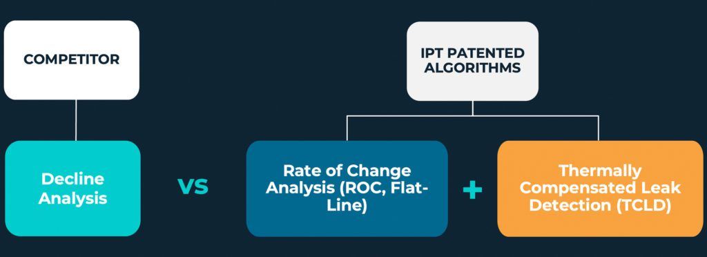
The results of the tests were gathered by the operator and presented to both parties (Figure 3). According to the major operator, tests performed using SureTec were 20% faster than the competitor’s tests. In addition to faster test validation, IPT provided a high level of integrity assurance using SureTec’s patented algorithms.
Be sure that your testing on integrity critical equipment and well barrier elements is accurate and effective with advanced leak detection through IPT SureTec Advanced Leak Detection Analysis! IPT’s Advanced Leak Detection Algorithms are available in the Standard, Advanced, and Premier tiers of SureTec. Contact us today to learn how our advanced analysis can help you.